80
13
15
R W B
R
R
L
L
1
2
1
2
O
O
B
W
R
O
B
W
R
O
B
W
R
O
B
W
R
O
B
W
R
AMPLIFIER
L1
L2
L3
1T1
1T2
1T3
2T1
2T2
2T3
3T1
3T2
3T3
DOOR
0 VOLTS
115 VOLTS
OVERLOADS
RESET
EMG. STOP
1TR
T.C.
1TR T.O.
1CR
STOP
START
STOP
STOP
START
START
IMPELLER
FEED SCREW
AGITATOR
1TR
2M
3M
3M
2M
1TR
1M
1CR
1 2 3
GRD.
G
9
8
7
6
5
4
3
2
1
11
10
12
13
14
15
16
17
2
WIRE NUMBER
3M
2M
1M
1CR
CUTTING
ENCLOSURE
FEED
ADAPTER
SENSORS
12 VDC
WIRING DIAGRAM # 61398
1
1
2
3
AGITATOR
MOTOR
FEED SCREW
MOTOR
IMPELLER
MOTOR
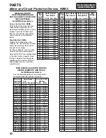
See charts on page 82 for fuse amperage.
See the chart on page 81 for current transformer windings.
PARTS
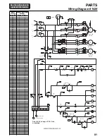
Wiring Diagram 61398
Summary of Contents for COMITROL 2100
Page 2: ......
Page 28: ...Addendum A 26 This page intentionally left blank...
Page 84: ...6 This page intentionally left blank...
Page 94: ...16 This page intentionally left blank...
Page 95: ...17 GENERAL INFORMATION...
Page 101: ...23 INSTALLATION...
Page 104: ...26 This page intentionally left blank...
Page 110: ...32 This page intentionally left blank...
Page 131: ...53 PARTS...
Page 132: ...54 This page intentionally left blank...
Page 134: ...56 PARTS Tools See the Addendum for updated information...
Page 138: ...60 PARTS Agitator Feed Screw See the Addendum for updated information...
Page 146: ...PARTS Motor and Drive Parts 68 See the Addendum for updated information...
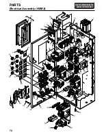
Page 148: ...PARTS Electrical Assembly NEMA 70 See the Addendum for updated information...
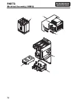
Page 152: ...PARTS Electrical Assembly CE compliant 74 See the Addendum for updated information...
Page 156: ...78 PARTS Electrical Assembly Switches See the Addendum for updated information...
Page 165: ......


