IDENTIFYING CUTTING HEADS
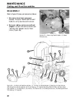
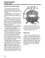
Cutting heads are identified by the
Urschel 5 digit part number and a corre-
sponding description number stamped or
embossed on the mounting lugs or columns
(Figure 32).
The first digit
(3) in the sample descrip-
tion number indicates the cutting head
height (actual dimension is 3.390" or 86.11
mm).
The letter
(K) refers to the type of head.
Type indicates the pattern and number of
columns, which contain the cutting edges.
There are several cutting head types avail-
able, such as A, B, J, K and M to produce
different cutting actions. Fewer columns will
produce a thicker particle. See page 21 for
additional information.
The next three numbers
(030) indicate
the metal thickness, in thousandths of an
inch, of the horizontal separators.
The last series of numbers
(120) indi-
cate the opening between the horizontal
separators in thousandths of an inch.
The “U” suffix
identifies an Urschalloy
cutting head; a description number without
a “U” indicates a fabricated cutting head.
Note that some cutting heads with the
same type designation (such as type A or
K) have a different pattern and number of
columns depending on whether the head is
cast (Urschalloy) or fabricated.
Special column
cutting heads are used
for producing coarse or large chunks.
These heads have fewer columns (vertical
cutting edges) and few, if any, horizontal
separators. Description numbers vary
slightly from those of standard cutting
heads. The number of columns is indicated
by the last number in the description, for
example, 3-060750-14 (14 columns). No
column number designation with a “P” after
cutting head height indicates 12 columns.
INSPECTION
Clean and inspect cutting heads for dam-
age and wear. Mounting surfaces and lugs
must be free from nicks, burrs and foreign
material to insure proper seating. Many sizes
of both Urschalloy and fabricated cutting
heads can be resharpened. Cutting heads
should be replaced when damaged or when
the quality of cut is no longer satisfactory.
See pages 65 & 67 for a list of available
cutting heads.
44
MAINTENANCE
Cutting Heads
3 K - 030 120 -
U
2
5
8
1
6
7
4
3
Figure 32 — Cutting head description number.
(1) Cutting Head Height, (2) Cutting Head Type,
(3) Thickness of Horizontal Separators, (4) Open-
ings Between Separators, (5) When present, indi-
cates Urschalloy, (6) Horizontal Separators,
(7) Columns, (8) Mounting Lugs
Summary of Contents for COMITROL 2100
Page 2: ......
Page 28: ...Addendum A 26 This page intentionally left blank...
Page 84: ...6 This page intentionally left blank...
Page 94: ...16 This page intentionally left blank...
Page 95: ...17 GENERAL INFORMATION...
Page 101: ...23 INSTALLATION...
Page 104: ...26 This page intentionally left blank...
Page 110: ...32 This page intentionally left blank...
Page 131: ...53 PARTS...
Page 132: ...54 This page intentionally left blank...
Page 134: ...56 PARTS Tools See the Addendum for updated information...
Page 138: ...60 PARTS Agitator Feed Screw See the Addendum for updated information...
Page 146: ...PARTS Motor and Drive Parts 68 See the Addendum for updated information...
Page 148: ...PARTS Electrical Assembly NEMA 70 See the Addendum for updated information...
Page 152: ...PARTS Electrical Assembly CE compliant 74 See the Addendum for updated information...
Page 156: ...78 PARTS Electrical Assembly Switches See the Addendum for updated information...
Page 165: ......


