DISASSEMBLY
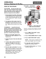
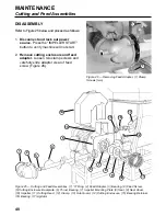
Refer to Figure 25 below and proceed as follows:
1.
Disconnect and lock out power
source.
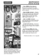
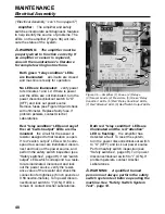
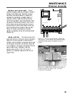
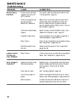
Press the “IMPELLER START”
button to verify machine will not start.
2.
Remove cutting enclosure and feed
adapter.
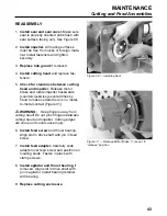
Loosen two clamp screws and
carefully slide adapter clear of feed
screw (Figure 26).
MAINTENANCE
Cutting and Feed Assemblies
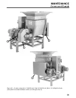
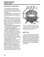
Figure 25 — Cutting and Feed Assemblies. (1) “O” Ring, (2) Feed Adapter, (3) Bearing, (4) Feed Screw,
(5) Cutting Enclosure Backplate, (6) Thrust Bearing, (7) Impeller Mounting Plate,(8) Seal, (9) Seal Cover,
(10) Impeller, (11) Cutting Head, (12) Clamp, (13) Hub Guard, (14) Cutting Enclosure, (15) Bearing Retainer,
(16) Bearing, (17) Agitator
1
3
2
40
Figure 26 — Removing Feed Adapter, (1) Clamp
Screws (two)
1
1
4
6
5
14
12
10
11
8
7
9
13
17
16
15
Summary of Contents for COMITROL 2100
Page 2: ......
Page 28: ...Addendum A 26 This page intentionally left blank...
Page 84: ...6 This page intentionally left blank...
Page 94: ...16 This page intentionally left blank...
Page 95: ...17 GENERAL INFORMATION...
Page 101: ...23 INSTALLATION...
Page 104: ...26 This page intentionally left blank...
Page 110: ...32 This page intentionally left blank...
Page 131: ...53 PARTS...
Page 132: ...54 This page intentionally left blank...
Page 134: ...56 PARTS Tools See the Addendum for updated information...
Page 138: ...60 PARTS Agitator Feed Screw See the Addendum for updated information...
Page 146: ...PARTS Motor and Drive Parts 68 See the Addendum for updated information...
Page 148: ...PARTS Electrical Assembly NEMA 70 See the Addendum for updated information...
Page 152: ...PARTS Electrical Assembly CE compliant 74 See the Addendum for updated information...
Page 156: ...78 PARTS Electrical Assembly Switches See the Addendum for updated information...
Page 165: ......


