TOSHIBA
TMPR3904F Rev. 2.0
50
7.6
Interrupts
In the TX3904, there are eight interrupt signals (INT[7:0]) and one non-
maskable interrupt signal (NMI*).
7.6.1
INT[7:0]
The INT[7:0] is a signal to request for an interrupt of the TX3904. It is used
when the external circuit requests an interrupt. The active status of INT[7:0]
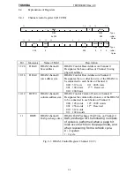
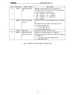
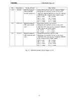
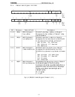
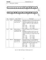
is set up in the CConR of the EBIF. There are four kinds in the active status--
the rising edge, the falling edge, the low level, and the high level.
The interrupt request by the INT[7:0] signal is arbitrated in the IRC and
informed to the TX39 Processor Core. When it is informed to the TX39
Processor Core, an interrupt exception occurs. The priority (interrupt level) of
the INT[7:1] interrupt can be set up in the register of the IRC. Interrupt
requests by INT[0] shall be informed to the TX39 Processor Core without going
via the IRC.
When the active status of the INT[7:0] is set up at the low level or the high
level, the interrupt request must be cleared at the origin of the interrupt
request. When the active status is set up at the rising edge or the falling edge,
clear the interrupt request in the EIClr field of the CConR.
7.6.2
NMI*
The NMI* is a non-maskable interrupt request signal. This interrupt cannot be
masked. When the NMI* is asserted, the TX39 Processor Core generates a
non-maskable interrupt exception.
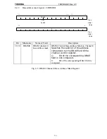
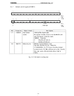
When the TX3904 built-in timer is operating as a watchdog timer and when
the WR bit of the CConR is 0, a non-maskable interrupt is generated when a
watchdog timer interrupt occurs.
7.7
Reset
By keeping the RESET* signal at low successively for 12 SYSCLK or more, the
TX3904 shall be initialized. All the values in the TX3904 internal registers
become the initial values. The TX39 Processor Core generates a reset
exception.
When the TX3904 built-in timer is operating as a watchdog timer and when
the WR bit of the CConR is 1, the TX3904 shall be reset when a watchdog
timer interrupt occurs.
Summary of Contents for TMPR3904F
Page 1: ...Users Manual 32bit RISC Microprocessor TX39 family TMPR3904F Rev 2 0 Jan 12 1998 ...
Page 2: ......
Page 9: ...Users Manual 01 1 INTRODUCTION 1 1 Overview ...
Page 11: ...Users Manual 03 1 3 Kind of accessing by the TX3904 ...
Page 12: ...Users Manual 04 1 4 Precautions in the TMPR3904F specification Don t set Don t use ...
Page 13: ...Users Manual 05 Do not use ...
Page 14: ...Users Manual 06 ...
Page 15: ...Users Manual 7 2 FEATURES n n n n n n n n n n n n n ...
Page 16: ...Users Manual 8 ...
Page 18: ...Users Manual 10 ...
Page 19: ...Users Manual 11 4 PINS 4 1 Positions of Pins ...
Page 20: ...Users Manual 12 ...
Page 21: ...Users Manual 13 4 2 Functions of Pins ...
Page 22: ...Users Manual 14 ...
Page 23: ...Users Manual 15 ...
Page 24: ...Users Manual 16 ...
Page 26: ...Users Manual 18 5 2 Register Map ...
Page 27: ...Users Manual 19 ...
Page 28: ...Users Manual 20 ...
Page 30: ...Users Manual 22 5 3 2 PIO2 and PIO1 ...
Page 32: ...Users Manual 24 5 3 4 Connection of external bus master 5 3 5 INT 7 0 active status clear ...
Page 33: ...Users Manual 25 5 3 6 INT 7 0 active status set up ...
Page 34: ...Users Manual 26 ...
Page 123: ...TOSHIBA TMPR3904F Rev 2 0 115 26 ...
Page 169: ...TOSHIBA TMPR3904F Rev 2 0 161 26 ...
Page 203: ...TOSHIBA TMPR3904F Rev 2 0 195 ...
Page 230: ......


