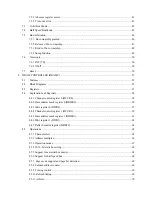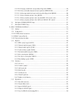
12.4.13 Error flag.............................................................................................................................. 189
12.4.14 Multi-controller system........................................................................................................ 189
12.5
Timing Explanations ........................................................................................................................ 191
12.5.1 Operation at the time of receiving (7 and 8 bit data length) .................................................. 191
12.5.2 Timing of SDMAREQ*/SMAACK* at the time of DMA I/F (at DMA level 4) .................. 191
12.5.3 Operation at the time of receiving (8 and 9 bit length multi-controller system; .................... 192
12.5.4 Operation at the time of receiving (8 and 9 bit length multi-controller system; .................... 192
12.5.5 Operation at the time of receiving (8 and 9 bit length multi-controller system; .................... 193
12.5.6 Operation at the time of transmitting ..................................................................................... 193
12.5.7 Transmit halt timing by CTS* ............................................................................................... 194
13 TIMERS/COUNTERS................................................................................................................................ 196
13.1
Features ........................................................................................................................................... 196
13.2
Block Diagrams............................................................................................................................... 196
13.3
Registers........................................................................................................................................... 198
13.3.1 Timer control registers 2, 1, and 0 (TCR2, 1, 0).................................................................... 200
13.3.2 Interval timer mode registers 0, 1, and 2 (ITMR2, 1, 0)........................................................ 202
13.3.3 Divider registers 2, 1, and 0 (CCDR2, 1, 0) .......................................................................... 203
13.3.4 Pulse generator mode registers 2 and 1 (PGMR2, 1)............................................................. 204
13.3.5 Watchdog timer mode register 2 (WTMR2).......................................................................... 205
13.3.6 Timer interrupt status registers 2, 1 and 0 (TISR2, 1, 0) ....................................................... 206
13.3.7 Compare registers A 2, 1 and 0 (CPRA2, 1, 0)...................................................................... 208
13.3.8 Compare registers B 2, 1 and 0 (CPRB2, 1, 0) ...................................................................... 208
13.3.9 Timer read registers 2, 1 and 0 (TRR2, 1, 0) ......................................................................... 209
13.4
Operations ........................................................................................................................................ 210
13.4.1 Interval timer mode................................................................................................................ 210
13.4.2 Pulse generator mode............................................................................................................. 213
13.4.3 Watchdog timer mode............................................................................................................ 215
13.5
Timing Explanations ........................................................................................................................ 216
13.5.1 Interval timer mode interrupt timing...................................................................................... 216
13.5.2 Pulse generator mode F/F output timing................................................................................ 217
13.5.3 Watchdog timer mode interrupt timing.................................................................................. 217
14 IO PORTS (PIO)......................................................................................................................................... 218
14.1
Set-Up of the Shared PIO’s.............................................................................................................. 218
14.2
Functions.......................................................................................................................................... 218
14.3
Registers........................................................................................................................................... 219
14.3.1 PIO data registers (PDR2, 1, 0) ............................................................................................. 220
14.3.2 PIO direction registers (POR2, 1, 0)..................................................................................... 221
Summary of Contents for TMPR3904F
Page 1: ...Users Manual 32bit RISC Microprocessor TX39 family TMPR3904F Rev 2 0 Jan 12 1998 ...
Page 2: ......
Page 9: ...Users Manual 01 1 INTRODUCTION 1 1 Overview ...
Page 11: ...Users Manual 03 1 3 Kind of accessing by the TX3904 ...
Page 12: ...Users Manual 04 1 4 Precautions in the TMPR3904F specification Don t set Don t use ...
Page 13: ...Users Manual 05 Do not use ...
Page 14: ...Users Manual 06 ...
Page 15: ...Users Manual 7 2 FEATURES n n n n n n n n n n n n n ...
Page 16: ...Users Manual 8 ...
Page 18: ...Users Manual 10 ...
Page 19: ...Users Manual 11 4 PINS 4 1 Positions of Pins ...
Page 20: ...Users Manual 12 ...
Page 21: ...Users Manual 13 4 2 Functions of Pins ...
Page 22: ...Users Manual 14 ...
Page 23: ...Users Manual 15 ...
Page 24: ...Users Manual 16 ...
Page 26: ...Users Manual 18 5 2 Register Map ...
Page 27: ...Users Manual 19 ...
Page 28: ...Users Manual 20 ...
Page 30: ...Users Manual 22 5 3 2 PIO2 and PIO1 ...
Page 32: ...Users Manual 24 5 3 4 Connection of external bus master 5 3 5 INT 7 0 active status clear ...
Page 33: ...Users Manual 25 5 3 6 INT 7 0 active status set up ...
Page 34: ...Users Manual 26 ...
Page 123: ...TOSHIBA TMPR3904F Rev 2 0 115 26 ...
Page 169: ...TOSHIBA TMPR3904F Rev 2 0 161 26 ...
Page 203: ...TOSHIBA TMPR3904F Rev 2 0 195 ...
Page 230: ......


