TOSHIBA
TMPR3904F Rev. 2.0
174
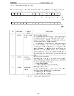
Bit
Mnemonic
Name of
Field
Description
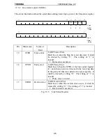
24
HSE
Hand shake
enable
Hand Shake Enable
Hand shake function control using the CTS.
0: Disable (Sending can always be done.)
1: Enable
22:21
SCS
Clock select
SIO Clock Select
Selects the serial transfer clock. The serial transfer
clock is a clock with the frequency 16 times of the
baud rate (bps).
00: T0 (Internal system clock)
01: Baud rate generator
1*: Set-up impossible
20
UEPS
Even parity
select
UART Even Parity Select
Makes the parity mode to the even number (Even)
parity.
0: Odd parity
1: Even parity
UPEN UEPS Description
1 0 Odd Parity
1 1 Even Parity
0 * Parity Disable
19
UPEN
Parity check
enable
UART Parity Enable
Must be 0 in the multi-control system mode
(UMODE=10, 11).
0: Disable parity check
1: Enable parity check
18
USBL
Stop bit
length
UART Stop Bit Length
Designates the Stop bit length.
0: 1-bit
1: 2-bit
17:16
UMODE
Mode
UART Mode
Sets up the SIO mode. A data length in the multi-
controller system mode includes a wake up bit.
00: 8-bit data length
01: 7-bit data length
10: Multi-controller 9-bit data length
11: Multi-controller 8-bit data length
Fig. 12-4 Line Control Register (2/2)
Summary of Contents for TMPR3904F
Page 1: ...Users Manual 32bit RISC Microprocessor TX39 family TMPR3904F Rev 2 0 Jan 12 1998 ...
Page 2: ......
Page 9: ...Users Manual 01 1 INTRODUCTION 1 1 Overview ...
Page 11: ...Users Manual 03 1 3 Kind of accessing by the TX3904 ...
Page 12: ...Users Manual 04 1 4 Precautions in the TMPR3904F specification Don t set Don t use ...
Page 13: ...Users Manual 05 Do not use ...
Page 14: ...Users Manual 06 ...
Page 15: ...Users Manual 7 2 FEATURES n n n n n n n n n n n n n ...
Page 16: ...Users Manual 8 ...
Page 18: ...Users Manual 10 ...
Page 19: ...Users Manual 11 4 PINS 4 1 Positions of Pins ...
Page 20: ...Users Manual 12 ...
Page 21: ...Users Manual 13 4 2 Functions of Pins ...
Page 22: ...Users Manual 14 ...
Page 23: ...Users Manual 15 ...
Page 24: ...Users Manual 16 ...
Page 26: ...Users Manual 18 5 2 Register Map ...
Page 27: ...Users Manual 19 ...
Page 28: ...Users Manual 20 ...
Page 30: ...Users Manual 22 5 3 2 PIO2 and PIO1 ...
Page 32: ...Users Manual 24 5 3 4 Connection of external bus master 5 3 5 INT 7 0 active status clear ...
Page 33: ...Users Manual 25 5 3 6 INT 7 0 active status set up ...
Page 34: ...Users Manual 26 ...
Page 123: ...TOSHIBA TMPR3904F Rev 2 0 115 26 ...
Page 169: ...TOSHIBA TMPR3904F Rev 2 0 161 26 ...
Page 203: ...TOSHIBA TMPR3904F Rev 2 0 195 ...
Page 230: ......


