TOSHIBA
TMPR3904F Rev. 2.0
122
26
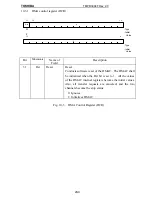
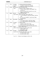
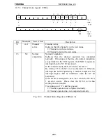
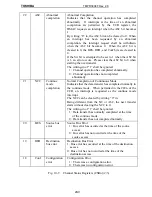
10.3.2 Channel control register (CCRn)
TrSiz
DIO
DAC
SAC
SIO
RelEn
SReq
Lev
PosE
ExR
SAM
DPS
1 7
1 8
2 0
1 9
2 4
2 1
2 2
2 3
2 5
3 0
3 1
1 6
1 5
0
: Type
: Initial
Value
: Type
: Initial
Value
Cont
Big
DOEn
DIEn
0
CIEn
AbIEn
NIEn
Stop
0
Str
W
W
R/W
R/W
R/W
R/W
R/W
R/W
R/W
R/W
R/W
R/W
R/W
R/W
R/W
R/W
R/W
R/W
R/W
0
1
0
1
1
1
0
0
0
0
0
0
0
0
00
00
00
00
1
2
1 4
1 3
1 2
1 0
1 1
9
8
7
6
5
4
3
R/W
0
Bit
Mnemonic
Name of Field
Description
31
Str
Channel start
Start
Starts the channel operation. By setting up this bit to 1,
the channel becomes the wait status and starts a data
transfer in response to a transfer request.
“1” is only valid to write in to the Str bit and the writing-in
of “0” is ignored. When read out, it is always “0.”
1: Starts the channel operation.
24
Stop
Channel stop
Stop
Completes the channel operation to change the channel to
the halt status. The SARn and the DARn maintain the
address following the address with which the last transfer
was made. The BCRn maintains the rest of the number of
transfer bytes.
When the channel is not in the wait status, writing-ins are
ignored.
“1” is only valid to write in to the Stop bit and the writing-
in of “0” is ignored. When read out, it is always “0.” Do
not set this bit “0” when the channel is not in the wait
satate.
When the Str bit and the Stop bit are simultaneously set up
to 1, the channel becomes the wait status.
1: Competes the channel operation.
23
NIEn
Normal
completion
interrupt
enable
Normal Completion Interrupt Enable
1: Grants a normal completion interrupt
0: Inhibits a normal completion interrupt
22
AbEn
Abnormal
completion
interrupt
enable
Abnormal Completion Interrupt Enable
1: Grants an abnormal completion interrupt
0: Inhibits an abnormal completion interrupt
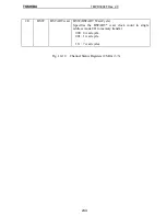
Fig. 10-4 Channel Control Registers (CCRn) (1/4)
Summary of Contents for TMPR3904F
Page 1: ...Users Manual 32bit RISC Microprocessor TX39 family TMPR3904F Rev 2 0 Jan 12 1998 ...
Page 2: ......
Page 9: ...Users Manual 01 1 INTRODUCTION 1 1 Overview ...
Page 11: ...Users Manual 03 1 3 Kind of accessing by the TX3904 ...
Page 12: ...Users Manual 04 1 4 Precautions in the TMPR3904F specification Don t set Don t use ...
Page 13: ...Users Manual 05 Do not use ...
Page 14: ...Users Manual 06 ...
Page 15: ...Users Manual 7 2 FEATURES n n n n n n n n n n n n n ...
Page 16: ...Users Manual 8 ...
Page 18: ...Users Manual 10 ...
Page 19: ...Users Manual 11 4 PINS 4 1 Positions of Pins ...
Page 20: ...Users Manual 12 ...
Page 21: ...Users Manual 13 4 2 Functions of Pins ...
Page 22: ...Users Manual 14 ...
Page 23: ...Users Manual 15 ...
Page 24: ...Users Manual 16 ...
Page 26: ...Users Manual 18 5 2 Register Map ...
Page 27: ...Users Manual 19 ...
Page 28: ...Users Manual 20 ...
Page 30: ...Users Manual 22 5 3 2 PIO2 and PIO1 ...
Page 32: ...Users Manual 24 5 3 4 Connection of external bus master 5 3 5 INT 7 0 active status clear ...
Page 33: ...Users Manual 25 5 3 6 INT 7 0 active status set up ...
Page 34: ...Users Manual 26 ...
Page 123: ...TOSHIBA TMPR3904F Rev 2 0 115 26 ...
Page 169: ...TOSHIBA TMPR3904F Rev 2 0 161 26 ...
Page 203: ...TOSHIBA TMPR3904F Rev 2 0 195 ...
Page 230: ......


