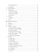
11 INTERRUPTS ............................................................................................................................................ 162
11.1
Features ............................................................................................................................................ 162
11.2
Configuration ................................................................................................................................... 163
11.3
Functions.......................................................................................................................................... 164
11.3.1 Interrupt sources .................................................................................................................... 164
11.3.2 Interrupt detection.................................................................................................................. 165
11.3.3 Interrupt priority arbitration process...................................................................................... 165
11.4
Registers........................................................................................................................................... 166
11.4.1 Register map .......................................................................................................................... 166
11.4.2 Interrupt status register (ISR) ................................................................................................ 167
11.4.3 Interrupt level registers (ILR3-ILR0) .................................................................................... 168
11.4.4 Interrupt mask register (IMR)................................................................................................ 169
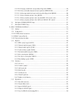
12 SERIAL PORTS (SIO) ............................................................................................................................... 170
12.1
Features ............................................................................................................................................ 170
12.2
Block Diagrams................................................................................................................................ 170
12.3
Registers........................................................................................................................................... 172
12.3.1 Line control register (SLCRn) ............................................................................................... 173
12.3.2 Line status register (SLSRn).................................................................................................. 175
12.3.3 DMA/Interrupt control register (SDICRn) ............................................................................ 176
12.3.4 DMA/Interrupt status register (SDISRn) ............................................................................... 178
12.3.5 FIFO control register (SFCRn) ............................................................................................. 180
12.3.6 Baudrate control register (SBGRn)........................................................................................ 181
12.3.7 Transmit FIFO buffer (TFIFOn)............................................................................................ 182
12.3.8 Receive FIFO buffer (SFIFOn).............................................................................................. 182
12.4
Operations ........................................................................................................................................ 183
12.4.1 Overview................................................................................................................................ 183
12.4.2 Data format ............................................................................................................................ 183
12.4.3 Serial clock generator ............................................................................................................ 185
12.4.4 Baudrate generator................................................................................................................. 185
12.4.5 Receiver Controller................................................................................................................ 187
12.4.6 Receiver shift register ............................................................................................................ 187
12.4.7 Receiver read buffer............................................................................................................... 187
12.4.8 Transmitter controller ............................................................................................................ 187
12.4.9 Transmitter shift register........................................................................................................ 187
12.4.10 Host I/F ................................................................................................................................ 187
12.4.11 Hand shake function ............................................................................................................ 188
12.4.12 Parity control........................................................................................................................ 189
Summary of Contents for TMPR3904F
Page 1: ...Users Manual 32bit RISC Microprocessor TX39 family TMPR3904F Rev 2 0 Jan 12 1998 ...
Page 2: ......
Page 9: ...Users Manual 01 1 INTRODUCTION 1 1 Overview ...
Page 11: ...Users Manual 03 1 3 Kind of accessing by the TX3904 ...
Page 12: ...Users Manual 04 1 4 Precautions in the TMPR3904F specification Don t set Don t use ...
Page 13: ...Users Manual 05 Do not use ...
Page 14: ...Users Manual 06 ...
Page 15: ...Users Manual 7 2 FEATURES n n n n n n n n n n n n n ...
Page 16: ...Users Manual 8 ...
Page 18: ...Users Manual 10 ...
Page 19: ...Users Manual 11 4 PINS 4 1 Positions of Pins ...
Page 20: ...Users Manual 12 ...
Page 21: ...Users Manual 13 4 2 Functions of Pins ...
Page 22: ...Users Manual 14 ...
Page 23: ...Users Manual 15 ...
Page 24: ...Users Manual 16 ...
Page 26: ...Users Manual 18 5 2 Register Map ...
Page 27: ...Users Manual 19 ...
Page 28: ...Users Manual 20 ...
Page 30: ...Users Manual 22 5 3 2 PIO2 and PIO1 ...
Page 32: ...Users Manual 24 5 3 4 Connection of external bus master 5 3 5 INT 7 0 active status clear ...
Page 33: ...Users Manual 25 5 3 6 INT 7 0 active status set up ...
Page 34: ...Users Manual 26 ...
Page 123: ...TOSHIBA TMPR3904F Rev 2 0 115 26 ...
Page 169: ...TOSHIBA TMPR3904F Rev 2 0 161 26 ...
Page 203: ...TOSHIBA TMPR3904F Rev 2 0 195 ...
Page 230: ......


