Page 185
TMP86PM29BUG
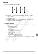
18.8 Recommended Oscillating Conditions
Note 1: A quartz resonator can be used for high-frequency oscillation only when V
DD
is 2.7 V or above. If V
DD
is below 2.7
V, use a ceramic resonator.
Note 2: To ensure stable oscillation, the resonator position, load capacitance, etc. must be appropriate. Because these
factors are greatly affected by board patterns, please be sure to evaluate operation on the board on which the
device will actually be mounted.
Note 3: For the resonators to be used with Toshiba microcontrollers, we recommend ceramic resonators manufactured by
Murata Manufacturing Co., Ltd.
For details, please visit the website of Murata at the following URL:
http://www.murata.com
18.9 Handling Precaution
- The solderability test conditions for lead-free products (indicated by the suffix G in product name) are shown
below.
1. When using the Sn-37Pb solder bath
Solder bath temperature = 230
°
C
Dipping time = 5 seconds
Number of times = once
R-type flux used
2. When using the Sn-3.0Ag-0.5Cu solder bath
Solder bath temperature = 245
°
C
Dipping time = 5 seconds
Number of times = once
R-type flux used
Note: The pass criteron of the above test is as follows:
Solderability rate until forming
≥
95 %
- When using the device (oscillator) in places exposed to high electric fields such as cathode-ray tubes, we
recommend electrically shielding the package in order to maintain normal operating condition.
(2) Low-frequency Oscillation
(1) High-frequency Oscillation
XIN
XOUT
C
2
C
1
XTIN
XTOUT
C
2
C
1
Summary of Contents for TLCS-870/C Series
Page 1: ...8 Bit Microcontroller TLCS 870 C Series TMP86PM29BUG ...
Page 6: ...TMP86PM29BUG ...
Page 7: ...Revision History Date Revision 2007 10 11 1 First Release 2008 8 29 2 Contents Revised ...
Page 9: ......
Page 15: ...vi ...
Page 19: ...Page 4 1 3 Block Diagram TMP86PM29BUG 1 3 Block Diagram Figure 1 2 Block Diagram ...
Page 23: ...Page 8 1 4 Pin Names and Functions TMP86PM29BUG ...
Page 48: ...Page 33 TMP86PM29BUG ...
Page 49: ...Page 34 2 Operational Description 2 3 Reset Circuit TMP86PM29BUG ...
Page 61: ...Page 46 3 Interrupt Control Circuit 3 8 External Interrupts TMP86PM29BUG ...
Page 81: ...Page 66 6 Watchdog Timer WDT 6 3 Address Trap TMP86PM29BUG ...
Page 135: ...Page 120 10 8 Bit TimerCounter TC5 TC6 10 1 Configuration TMP86PM29BUG ...
Page 145: ...Page 130 11 Asynchronous Serial interface UART 11 9 Status Flag TMP86PM29BUG ...
Page 165: ...Page 150 13 10 bit AD Converter ADC 13 6 Precautions about AD Converter TMP86PM29BUG ...
Page 183: ...Page 168 15 LCD Driver 15 4 Control Method of LCD Driver TMP86PM29BUG ...
Page 201: ...Page 186 18 Electrical Characteristics 18 9 Handling Precaution TMP86PM29BUG ...
Page 203: ...Page 188 19 Package Dimensions TMP86PM29BUG ...
Page 205: ......

