Page 40
3. Interrupt Control Circuit
3.4 Interrupt Sequence
TMP86PM29BUG
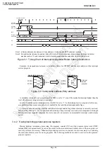
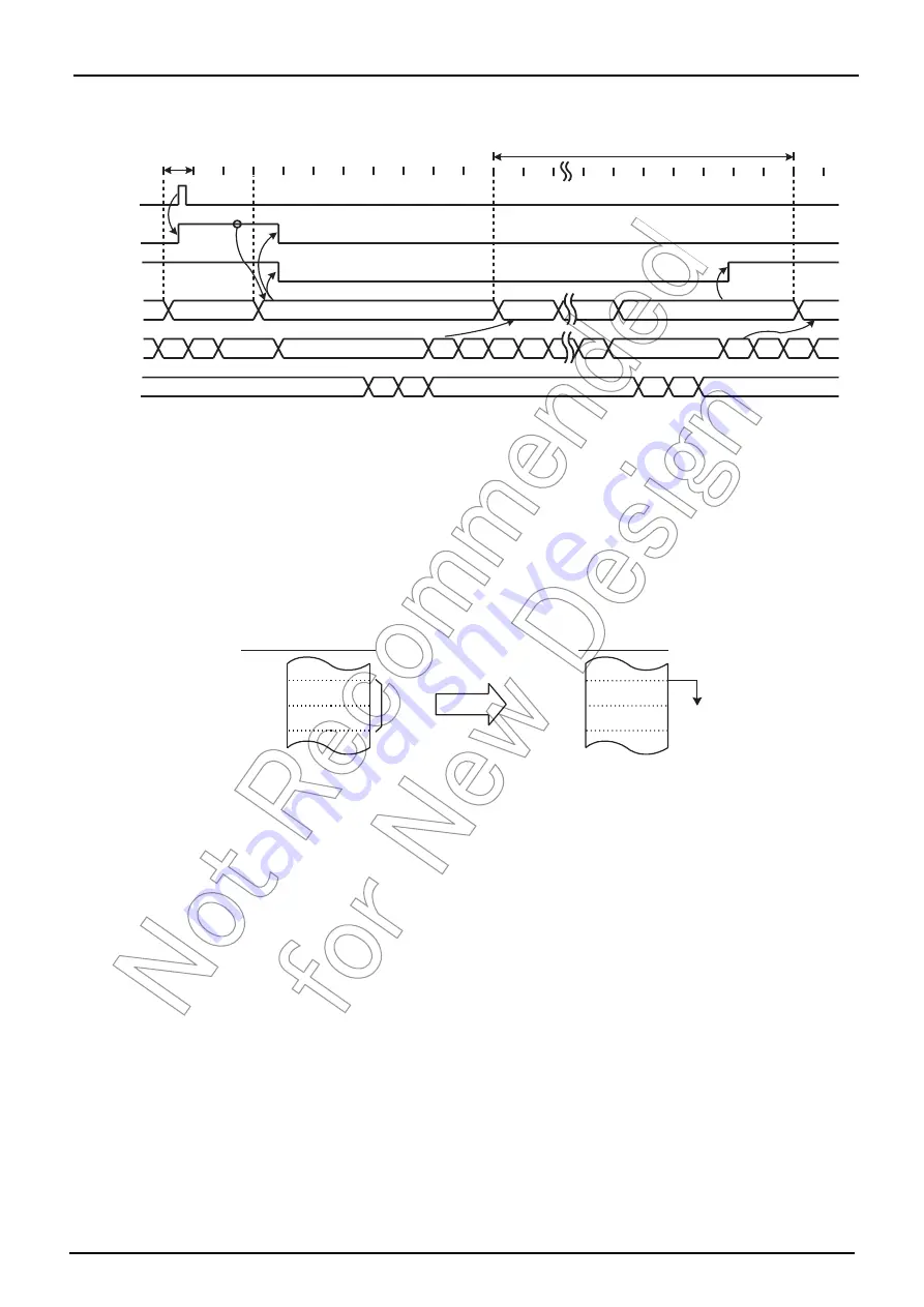
Note 1: a: Return address entry address, b: Entry address, c: Address which RETI instruction is stored
Note 2: On condition that interrupt is enabled, it takes 38/fc [s] or 38/fs [s] at maximum (If the interrupt latch is set at the first
machine cycle on 10 cycle instruction) to start interrupt acceptance processing since its interrupt latch is set.
Figure 3-1 Timing Chart of Interrupt Acceptance/Return Interrupt Instruction
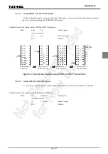
Example: Correspondence between vector table address for INTTBT and the entry address of the interrupt
service program
Figure 3-2 Vector table address,Entry address
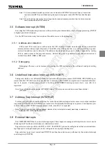
A maskable interrupt is not accepted until the IMF is set to “1” even if the maskable interrupt higher than the
level of current servicing interrupt is requested.
In order to utilize nested interrupt service, the IMF is set to “1” in the interrupt service program. In this case,
acceptable interrupt sources are selectively enabled by the individual interrupt enable flags.
To avoid overloaded nesting, clear the individual interrupt enable flag whose interrupt is currently serviced,
before setting IMF to “1”. As for non-maskable interrupt, keep interrupt service shorten compared with length
between interrupt requests; otherwise the status cannot be recovered as non-maskable interrupt would simply
nested.
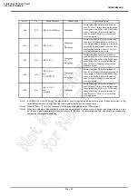
3.4.2
Saving/restoring general-purpose registers
During interrupt acceptance processing, the program counter (PC) and the program status word (PSW,
includes IMF) are automatically saved on the stack, but the accumulator and others are not. These registers are
saved by software if necessary. When multiple interrupt services are nested, it is also necessary to avoid using
the same data memory area for saving registers. The following methods are used to save/restore the general-
purpose registers.
a
b
a
c
+
1
Execute
instruction
SP
PC
Execute
instruction
n
n
−
2
n - 3
n
−
2
n
−
1
n
−
1
n
a
+
2
a
+
1
c
+
2
b + 3
b
+
2
b
+
1
a
+
1
a
a
−
1
Execute RETI instruction
Interrupt acceptance
Execute
instruction
Interrupt service task
1-machine cycle
Interrupt
request
Interrupt
latch (IL)
IMF
D2H
03H
D203H
D204H
06H
Vector table address
Entry address
0FH
Vector
Interrupt
service
program
FFF2H
FFF3H
Summary of Contents for TLCS-870/C Series
Page 1: ...8 Bit Microcontroller TLCS 870 C Series TMP86PM29BUG ...
Page 6: ...TMP86PM29BUG ...
Page 7: ...Revision History Date Revision 2007 10 11 1 First Release 2008 8 29 2 Contents Revised ...
Page 9: ......
Page 15: ...vi ...
Page 19: ...Page 4 1 3 Block Diagram TMP86PM29BUG 1 3 Block Diagram Figure 1 2 Block Diagram ...
Page 23: ...Page 8 1 4 Pin Names and Functions TMP86PM29BUG ...
Page 48: ...Page 33 TMP86PM29BUG ...
Page 49: ...Page 34 2 Operational Description 2 3 Reset Circuit TMP86PM29BUG ...
Page 61: ...Page 46 3 Interrupt Control Circuit 3 8 External Interrupts TMP86PM29BUG ...
Page 81: ...Page 66 6 Watchdog Timer WDT 6 3 Address Trap TMP86PM29BUG ...
Page 135: ...Page 120 10 8 Bit TimerCounter TC5 TC6 10 1 Configuration TMP86PM29BUG ...
Page 145: ...Page 130 11 Asynchronous Serial interface UART 11 9 Status Flag TMP86PM29BUG ...
Page 165: ...Page 150 13 10 bit AD Converter ADC 13 6 Precautions about AD Converter TMP86PM29BUG ...
Page 183: ...Page 168 15 LCD Driver 15 4 Control Method of LCD Driver TMP86PM29BUG ...
Page 201: ...Page 186 18 Electrical Characteristics 18 9 Handling Precaution TMP86PM29BUG ...
Page 203: ...Page 188 19 Package Dimensions TMP86PM29BUG ...
Page 205: ......

