Page 20
2. Operational Description
2.2 System Clock Controller
TMP86PM29BUG
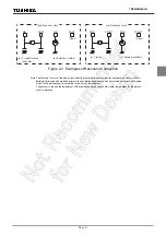
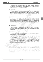
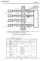
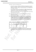
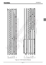
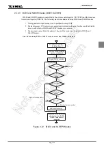
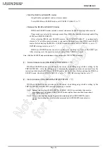
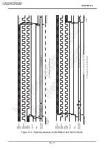
STOP mode is released by the following sequence.
1. In the dual-clock mode, when returning to NORMAL2, both the high-frequency and low-
frequency clock oscillators are turned on; when returning to SLOW1 mode, only the low-
frequency clock oscillator is turned on. In the single-clock mode, only the high-frequency
clock oscillator is turned on.
2. A warm-up period is inserted to allow oscillation time to stabilize. During warm up, all
internal operations remain halted. Four different warm-up times can be selected with the
SYSCR1<WUT> in accordance with the resonator characteristics.
3. When the warm-up time has elapsed, normal operation resumes with the instruction follow-
ing the STOP mode start instruction.
Note 1: When the STOP mode is released, the start is made after the prescaler and the divider of the
timing generator are cleared to "0".
Note 2: STOP mode can also be released by inputting low level on the
RESET
pin, which immediately
performs the normal reset operation.
Note 3: When STOP mode is released with a low hold voltage, the following cautions must be observed.
The power supply voltage must be at the operating voltage level before releasing STOP mode.
The
RESET
pin input must also be “H” level, rising together with the power supply voltage. In this
case, if an external time constant circuit has been connected, the
RESET
pin input voltage will
increase at a slower pace than the power supply voltage. At this time, there is a danger that a
reset may occur if input voltage level of the
RESET
pin drops below the non-inverting high-level
input voltage (Hysteresis input).
Note 1: The warm-up time is obtained by dividing the basic clock by the divider. Therefore, the warm-up
time may include a certain amount of error if there is any fluctuation of the oscillation frequency
when STOP mode is released. Thus, the warm-up time must be considered as an approximate
value.
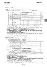
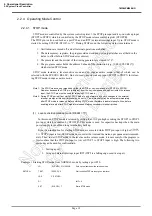
Table 2-2 Warm-up Time Example (at fc = 16.0 MHz, fs = 32.768 kHz)
WUT
Warm-up Time [ms]
Return to NORMAL Mode
Return to SLOW Mode
00
01
10
11
12.288
4.096
3.072
1.024
750
250
5.85
1.95
Summary of Contents for TLCS-870/C Series
Page 1: ...8 Bit Microcontroller TLCS 870 C Series TMP86PM29BUG ...
Page 6: ...TMP86PM29BUG ...
Page 7: ...Revision History Date Revision 2007 10 11 1 First Release 2008 8 29 2 Contents Revised ...
Page 9: ......
Page 15: ...vi ...
Page 19: ...Page 4 1 3 Block Diagram TMP86PM29BUG 1 3 Block Diagram Figure 1 2 Block Diagram ...
Page 23: ...Page 8 1 4 Pin Names and Functions TMP86PM29BUG ...
Page 48: ...Page 33 TMP86PM29BUG ...
Page 49: ...Page 34 2 Operational Description 2 3 Reset Circuit TMP86PM29BUG ...
Page 61: ...Page 46 3 Interrupt Control Circuit 3 8 External Interrupts TMP86PM29BUG ...
Page 81: ...Page 66 6 Watchdog Timer WDT 6 3 Address Trap TMP86PM29BUG ...
Page 135: ...Page 120 10 8 Bit TimerCounter TC5 TC6 10 1 Configuration TMP86PM29BUG ...
Page 145: ...Page 130 11 Asynchronous Serial interface UART 11 9 Status Flag TMP86PM29BUG ...
Page 165: ...Page 150 13 10 bit AD Converter ADC 13 6 Precautions about AD Converter TMP86PM29BUG ...
Page 183: ...Page 168 15 LCD Driver 15 4 Control Method of LCD Driver TMP86PM29BUG ...
Page 201: ...Page 186 18 Electrical Characteristics 18 9 Handling Precaution TMP86PM29BUG ...
Page 203: ...Page 188 19 Package Dimensions TMP86PM29BUG ...
Page 205: ......

