Page 16
2. Operational Description
2.2 System Clock Controller
TMP86PM29BUG
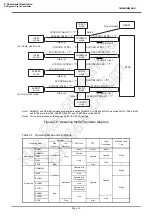
Note 1: NORMAL1 and NORMAL2 modes are generically called NORMAL; SLOW1 and SLOW2 are called SLOW; IDLE0, IDLE1
and IDLE2 are called IDLE; SLEEP0, SLEEP1 and SLEEP2 are called SLEEP.
Note 2: The mode is released by falling edge of TBTCR<TBTCK> setting.
Figure 2-6 Operating Mode Transition Diagram
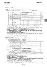
Table 2-1 Operating Mode and Conditions
Operating Mode
Oscillator
CPU Core
TBT
Other
Peripherals
Machine Cycle
Time
High
Frequency
Low
Frequency
Single clock
RESET
Oscillation
Stop
Reset
Reset
Reset
4/fc [s]
NORMAL1
Operate
Operate
Operate
IDLE1
Halt
IDLE0
Halt
STOP
Stop
Halt
–
Dual clock
NORMAL2
Oscillation
Oscillation
Operate with
high frequency
Operate
Operate
4/fc [s]
IDLE2
Halt
SLOW2
Operate with
low frequency
4/fs [s]
SLEEP2
Halt
SLOW1
Stop
Operate with
low frequency
SLEEP1
Halt
SLEEP0
Halt
STOP
Stop
Halt
–
Note 2
SYSCR2<XEN> = "1"
STOP pin input
STOP pin input
STOP pin input
Interrupt
Interrupt
SYSCR2<XEN> = "0"
SYSCR2<SYSCK> = "1"
SYSCR2<XTEN> = "0"
SYSCR2<SYSCK> = "0"
SYSCR1<STOP> = "1"
SYSCR1<STOP> = "1"
SYSCR1<STOP> = "1"
SYSCR2<IDLE> = "1"
SYSCR2<IDLE> = "1"
Interrupt
SYSCR2<IDLE> = "1"
SYSCR2<IDLE> = "1"
Interrupt
SYSCR2<TGHALT> = "1"
Reset release
NORMAL1
mode
IDLE0
mode
(a) Single-clock mode
IDLE1
mode
NORMAL2
mode
IDLE2
mode
SYSCR2<XTEN> = "1"
SLOW2
mode
SLEEP2
mode
SLOW1
mode
SLEEP1
mode
SLEEP0
mode
RESET
(b) Dual-clock mode
STOP
SYSCR2<TGHALT> = "1"
Note 2
Summary of Contents for TLCS-870/C Series
Page 1: ...8 Bit Microcontroller TLCS 870 C Series TMP86PM29BUG ...
Page 6: ...TMP86PM29BUG ...
Page 7: ...Revision History Date Revision 2007 10 11 1 First Release 2008 8 29 2 Contents Revised ...
Page 9: ......
Page 15: ...vi ...
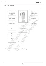
Page 19: ...Page 4 1 3 Block Diagram TMP86PM29BUG 1 3 Block Diagram Figure 1 2 Block Diagram ...
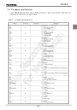
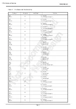
Page 23: ...Page 8 1 4 Pin Names and Functions TMP86PM29BUG ...
Page 48: ...Page 33 TMP86PM29BUG ...
Page 49: ...Page 34 2 Operational Description 2 3 Reset Circuit TMP86PM29BUG ...
Page 61: ...Page 46 3 Interrupt Control Circuit 3 8 External Interrupts TMP86PM29BUG ...
Page 81: ...Page 66 6 Watchdog Timer WDT 6 3 Address Trap TMP86PM29BUG ...
Page 135: ...Page 120 10 8 Bit TimerCounter TC5 TC6 10 1 Configuration TMP86PM29BUG ...
Page 145: ...Page 130 11 Asynchronous Serial interface UART 11 9 Status Flag TMP86PM29BUG ...
Page 165: ...Page 150 13 10 bit AD Converter ADC 13 6 Precautions about AD Converter TMP86PM29BUG ...
Page 183: ...Page 168 15 LCD Driver 15 4 Control Method of LCD Driver TMP86PM29BUG ...
Page 201: ...Page 186 18 Electrical Characteristics 18 9 Handling Precaution TMP86PM29BUG ...
Page 203: ...Page 188 19 Package Dimensions TMP86PM29BUG ...
Page 205: ......

