Page 10
2. Operational Description
2.2 System Clock Controller
TMP86PM29BUG
The data memory contents become unstable when the power supply is turned on; therefore, the data memory
should be initialized by an initialization routine.
2.2
System Clock Controller
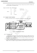
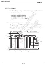
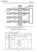
The system clock controller consists of a clock generator, a timing generator, and a standby controller.
Figure 2-2 System Colck Control
2.2.1
Clock Generator
The clock generator generates the basic clock which provides the system clocks supplied to the CPU core
and peripheral hardware. It contains two oscillation circuits: One for the high-frequency clock and one for the
low-frequency clock. Power consumption can be reduced by switching of the standby controller to low-power
operation based on the low-frequency clock.
The high-frequency (fc) clock and low-frequency (fs) clock can easily be obtained by connecting a resonator
between the XIN/XOUT and XTIN/XTOUT pins respectively. Clock input from an external oscillator is also
possible. In this case, external clock is applied to XIN/XTIN pin with XOUT/XTOUT pin not connected.
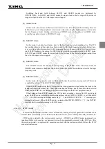
Example :Clears RAM to “00H”. (TMP86PM29BUG)
LD
HL, 0040H
; Start address setup
LD
A, H
; Initial value (00H) setup
LD
BC, 05FFH
SRAMCLR:
LD
(HL), A
INC
HL
DEC
BC
JRS
F, SRAMCLR
TBTCR
SYSCR2
SYSCR1
XIN
XOUT
XTIN
XTOUT
fc
0036H
0038H
0039H
fs
Timing generator control register
Timing
generator
Standby controller
System clocks
Clock generator control
High-frequency
clock oscillator
Low-frequency
clock oscillator
Clock
generator
System control registers
Summary of Contents for TLCS-870/C Series
Page 1: ...8 Bit Microcontroller TLCS 870 C Series TMP86PM29BUG ...
Page 6: ...TMP86PM29BUG ...
Page 7: ...Revision History Date Revision 2007 10 11 1 First Release 2008 8 29 2 Contents Revised ...
Page 9: ......
Page 15: ...vi ...
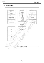
Page 19: ...Page 4 1 3 Block Diagram TMP86PM29BUG 1 3 Block Diagram Figure 1 2 Block Diagram ...
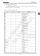
Page 23: ...Page 8 1 4 Pin Names and Functions TMP86PM29BUG ...
Page 48: ...Page 33 TMP86PM29BUG ...
Page 49: ...Page 34 2 Operational Description 2 3 Reset Circuit TMP86PM29BUG ...
Page 61: ...Page 46 3 Interrupt Control Circuit 3 8 External Interrupts TMP86PM29BUG ...
Page 81: ...Page 66 6 Watchdog Timer WDT 6 3 Address Trap TMP86PM29BUG ...
Page 135: ...Page 120 10 8 Bit TimerCounter TC5 TC6 10 1 Configuration TMP86PM29BUG ...
Page 145: ...Page 130 11 Asynchronous Serial interface UART 11 9 Status Flag TMP86PM29BUG ...
Page 165: ...Page 150 13 10 bit AD Converter ADC 13 6 Precautions about AD Converter TMP86PM29BUG ...
Page 183: ...Page 168 15 LCD Driver 15 4 Control Method of LCD Driver TMP86PM29BUG ...
Page 201: ...Page 186 18 Electrical Characteristics 18 9 Handling Precaution TMP86PM29BUG ...
Page 203: ...Page 188 19 Package Dimensions TMP86PM29BUG ...
Page 205: ......

