Page 64
6. Watchdog Timer (WDT)
6.3 Address Trap
TMP86PM29BUG
6.3
Address Trap
The Watchdog Timer Control Register 1 and 2 share the addresses with the control registers to generate address
traps.
6.3.1
Selection of Address Trap in Internal RAM (ATAS)
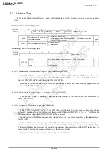
WDTCR1<ATAS> specifies whether or not to generate address traps in the internal RAM area. To execute
an instruction in the internal RAM area, clear WDTCR1<ATAS> to “0”. To enable the WDTCR1<ATAS> set-
ting, set WDTCR1<ATAS> and then write D2H to WDTCR2.
Executing an instruction in the SFR or DBR area generates an address trap unconditionally regardless of the
setting in WDTCR1<ATAS>.
6.3.2
Selection of Operation at Address Trap (ATOUT)
When an address trap is generated, either the interrupt request or the reset request can be selected by
WDTCR1<ATOUT>.
6.3.3
Address Trap Interrupt (INTATRAP)
While WDTCR1<ATOUT> is “0”, if the CPU should start looping for some cause such as noise and an
attempt be made to fetch an instruction from the on-chip RAM (while WDTCR1<ATAS> is “1”), DBR or the
SFR area, address trap interrupt (INTATRAP) will be generated.
An address trap interrupt is a non-maskable interrupt which can be accepted regardless of the interrupt mas-
ter flag (IMF).
When an address trap interrupt is generated while the other interrupt including an address trap interrupt is
already accepted, the new address trap is processed immediately and the previous interrupt is held pending.
Therefore, if address trap interrupts are generated continuously without execution of the RETN instruction, too
many levels of nesting may cause a malfunction of the microcontroller.
To generate address trap interrupts, set the stack pointer beforehand.
Watchdog Timer Control Register 1
WDTCR1
(0034H)
7
6
5
4
3
2
1
0
ATAS
ATOUT
(WDTEN)
(WDTT)
(WDTOUT)
(Initial value: **11 1001)
ATAS
Select address trap generation in
the internal RAM area
0: Generate no address trap
1: Generate address traps (After setting ATAS to “1”, writing the control code
D2H to WDTCR2 is required)
Write
only
ATOUT
Select operation at address trap
0: Interrupt request
1: Reset request
Watchdog Timer Control Register 2
WDTCR2
(0035H)
7
6
5
4
3
2
1
0
(Initial value: **** ****)
WDTCR2
Write
Watchdog timer control code
and address trap area control
code
D2H: Enable address trap area selection (ATRAP control code)
4EH: Clear the watchdog timer binary counter (WDT clear code)
B1H: Disable the watchdog timer (WDT disable code)
Others: Invalid
Write
only
Summary of Contents for TLCS-870/C Series
Page 1: ...8 Bit Microcontroller TLCS 870 C Series TMP86PM29BUG ...
Page 6: ...TMP86PM29BUG ...
Page 7: ...Revision History Date Revision 2007 10 11 1 First Release 2008 8 29 2 Contents Revised ...
Page 9: ......
Page 15: ...vi ...
Page 19: ...Page 4 1 3 Block Diagram TMP86PM29BUG 1 3 Block Diagram Figure 1 2 Block Diagram ...
Page 23: ...Page 8 1 4 Pin Names and Functions TMP86PM29BUG ...
Page 48: ...Page 33 TMP86PM29BUG ...
Page 49: ...Page 34 2 Operational Description 2 3 Reset Circuit TMP86PM29BUG ...
Page 61: ...Page 46 3 Interrupt Control Circuit 3 8 External Interrupts TMP86PM29BUG ...
Page 81: ...Page 66 6 Watchdog Timer WDT 6 3 Address Trap TMP86PM29BUG ...
Page 135: ...Page 120 10 8 Bit TimerCounter TC5 TC6 10 1 Configuration TMP86PM29BUG ...
Page 145: ...Page 130 11 Asynchronous Serial interface UART 11 9 Status Flag TMP86PM29BUG ...
Page 165: ...Page 150 13 10 bit AD Converter ADC 13 6 Precautions about AD Converter TMP86PM29BUG ...
Page 183: ...Page 168 15 LCD Driver 15 4 Control Method of LCD Driver TMP86PM29BUG ...
Page 201: ...Page 186 18 Electrical Characteristics 18 9 Handling Precaution TMP86PM29BUG ...
Page 203: ...Page 188 19 Package Dimensions TMP86PM29BUG ...
Page 205: ......


