Page 26
2. Operational Description
2.2 System Clock Controller
TMP86PM29BUG
•
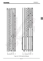
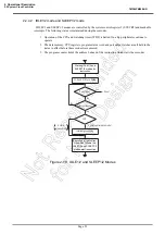
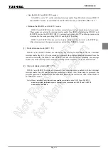
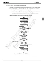
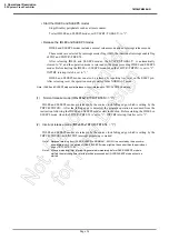
Start the IDLE0 and SLEEP0 modes
Stop (Disable) peripherals such as a timer counter.
To start IDLE0 and SLEEP0 modes, set SYSCR2<TGHALT> to “1”.
•
Release the IDLE0 and SLEEP0 modes
IDLE0 and SLEEP0 modes include a normal release mode and an interrupt release mode.
These modes are selected by interrupt master flag (IMF), the individual interrupt enable flag
of TBT and TBTCR<TBTEN>.
After releasing IDLE0 and SLEEP0 modes, the SYSCR2<TGHALT> is automatically
cleared to “0” and the operation mode is returned to the mode preceding IDLE0 and SLEEP0
modes. Before starting the IDLE0 or SLEEP0 mode, when the TBTCR<TBTEN> is set to “1”,
INTTBT interrupt latch is set to “1”.
IDLE0 and SLEEP0 modes can also be released by inputting low level on the
RESET
pin.
After releasing reset, the operation mode is started from NORMAL1 mode.
Note: IDLE0 and SLEEP0 modes start/release without reference to TBTCR<TBTEN> setting.
(1)
Normal release mode (IMF
•
EF6
•
TBTCR<TBTEN> = “0”)
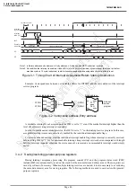
IDLE0 and SLEEP0 modes are released by the source clock falling edge, which is setting by the
TBTCR<TBTCK>. After the falling edge is detected, the program operation is resumed from the
instruction following the IDLE0 and SLEEP0 modes start instruction. Before starting the IDLE0 or
SLEEP0 mode, when the TBTCR<TBTEN> is set to “1”, INTTBT interrupt latch is set to “1”.
(2)
Interrupt release mode (IMF
•
EF6
•
TBTCR<TBTEN> = “1”)
IDLE0 and SLEEP0 modes are released by the source clock falling edge, which is setting by the
TBTCR<TBTCK> and INTTBT interrupt processing is started.
Note 1: Because returning from IDLE0, SLEEP0 to NORMAL1, SLOW1 is executed by the asynchro-
nous internal clock, the period of IDLE0, SLEEP0 mode might be the shorter than the period set-
ting by TBTCR<TBTCK>.
Note 2: When a watchdog timer interrupt is generated immediately before IDLE0/SLEEP0 mode is
started, the watchdog timer interrupt will be processed but IDLE0/SLEEP0 mode will not be
started.
Summary of Contents for TLCS-870/C Series
Page 1: ...8 Bit Microcontroller TLCS 870 C Series TMP86PM29BUG ...
Page 6: ...TMP86PM29BUG ...
Page 7: ...Revision History Date Revision 2007 10 11 1 First Release 2008 8 29 2 Contents Revised ...
Page 9: ......
Page 15: ...vi ...
Page 19: ...Page 4 1 3 Block Diagram TMP86PM29BUG 1 3 Block Diagram Figure 1 2 Block Diagram ...
Page 23: ...Page 8 1 4 Pin Names and Functions TMP86PM29BUG ...
Page 48: ...Page 33 TMP86PM29BUG ...
Page 49: ...Page 34 2 Operational Description 2 3 Reset Circuit TMP86PM29BUG ...
Page 61: ...Page 46 3 Interrupt Control Circuit 3 8 External Interrupts TMP86PM29BUG ...
Page 81: ...Page 66 6 Watchdog Timer WDT 6 3 Address Trap TMP86PM29BUG ...
Page 135: ...Page 120 10 8 Bit TimerCounter TC5 TC6 10 1 Configuration TMP86PM29BUG ...
Page 145: ...Page 130 11 Asynchronous Serial interface UART 11 9 Status Flag TMP86PM29BUG ...
Page 165: ...Page 150 13 10 bit AD Converter ADC 13 6 Precautions about AD Converter TMP86PM29BUG ...
Page 183: ...Page 168 15 LCD Driver 15 4 Control Method of LCD Driver TMP86PM29BUG ...
Page 201: ...Page 186 18 Electrical Characteristics 18 9 Handling Precaution TMP86PM29BUG ...
Page 203: ...Page 188 19 Package Dimensions TMP86PM29BUG ...
Page 205: ......

