Page 2
1.1 Features
TMP86PM29BUG
7. 8-bit timer counter : 4 ch
- Timer, Event counter, Programmable divider output (PDO),
Pulse width modulation (PWM) output,
Programmable pulse generation (PPG) modes
8. 8-bit UART/SIO : 1 ch
9. 10-bit successive approximation type AD converter
- Analog input: 8 ch
10. Key-on wakeup : 4 ch
11. LCD driver/controller
Built-in voltage booster for LCD driver With display memory
LCD direct drive capability (MAX 32 seg
×
4 com)
1/4,1/3,1/2duties or static drive are programmably selectable
12. Clock operation
Single clock mode
Dual clock mode
13. Low power consumption operation
STOP mode: Oscillation stops. (Battery/Capacitor back-up.)
SLOW1 mode: Low power consumption operation using low-frequency clock.(High-frequency clock
stop.)
SLOW2 mode: Low power consumption operation using low-frequency clock.(High-frequency clock
oscillate.)
IDLE0 mode: CPU stops, and only the Time-Based-Timer(TBT) on peripherals operate using high fre-
quency clock. Release by falling edge of the source clock which is set by TBTCR<TBTCK>.
IDLE1 mode: CPU stops and peripherals operate using high frequency clock. Release by interru-
puts(CPU restarts).
IDLE2 mode: CPU stops and peripherals operate using high and low frequency clock. Release by inter-
ruputs. (CPU restarts).
SLEEP0 mode: CPU stops, and only the Time-Based-Timer(TBT) on peripherals operate using low fre-
quency clock.Release by falling edge of the source clock which is set by TBTCR<TBTCK>.
SLEEP1 mode: CPU stops, and peripherals operate using low frequency clock. Release by interru-
put.(CPU restarts).
SLEEP2 mode: CPU stops and peripherals operate using high and low frequency clock. Release by
interruput.
14. Wide operation voltage:
4.5
V to
5.5
V at
16
MHz /32.768 kHz
2.7
V to
5.5
V at
8
MHz /32.768 kHz
1.8
V to
5.5
V at
4.2
MHz /32.768 kHz
Summary of Contents for TLCS-870/C Series
Page 1: ...8 Bit Microcontroller TLCS 870 C Series TMP86PM29BUG ...
Page 6: ...TMP86PM29BUG ...
Page 7: ...Revision History Date Revision 2007 10 11 1 First Release 2008 8 29 2 Contents Revised ...
Page 9: ......
Page 15: ...vi ...
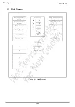
Page 19: ...Page 4 1 3 Block Diagram TMP86PM29BUG 1 3 Block Diagram Figure 1 2 Block Diagram ...
Page 23: ...Page 8 1 4 Pin Names and Functions TMP86PM29BUG ...
Page 48: ...Page 33 TMP86PM29BUG ...
Page 49: ...Page 34 2 Operational Description 2 3 Reset Circuit TMP86PM29BUG ...
Page 61: ...Page 46 3 Interrupt Control Circuit 3 8 External Interrupts TMP86PM29BUG ...
Page 81: ...Page 66 6 Watchdog Timer WDT 6 3 Address Trap TMP86PM29BUG ...
Page 135: ...Page 120 10 8 Bit TimerCounter TC5 TC6 10 1 Configuration TMP86PM29BUG ...
Page 145: ...Page 130 11 Asynchronous Serial interface UART 11 9 Status Flag TMP86PM29BUG ...
Page 165: ...Page 150 13 10 bit AD Converter ADC 13 6 Precautions about AD Converter TMP86PM29BUG ...
Page 183: ...Page 168 15 LCD Driver 15 4 Control Method of LCD Driver TMP86PM29BUG ...
Page 201: ...Page 186 18 Electrical Characteristics 18 9 Handling Precaution TMP86PM29BUG ...
Page 203: ...Page 188 19 Package Dimensions TMP86PM29BUG ...
Page 205: ......

