background image

74 


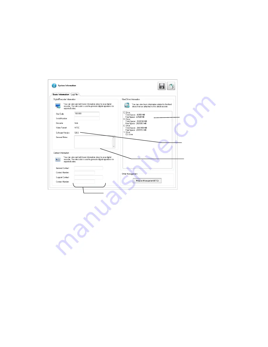
System Information 

The 

Log Management

 window provides you the options to overwrite log files or schedule log deletion. 


Basic Information 

The Information display allows users to define the site code necessary for connecting to remote software, save comments relative to the 
recorder, store tech support and contact number information, and see the currently running server software version. 


Site Code – 

A user-specified unique identification name used by other recorder software to identify the recorder. (Remote, Emergency 

Agent, SCS, Digital Signature Verifier)


Contact Information – 

Attach contact information as a digital signature to exported video. 


Other Management –

 Click Program Management to access 

External Program Management


   User-Defined Contact Numbers 

   Total HDD /Available HDD 

   Space 

 User Entered 
Comments 

   Currently running 
   software version 

Summary of Contents for Surveillix XVSv16-240-X

Page 1: ...1 Digital Video Recorder XVSv User Manual model no Please carefully read these instructions before using this product Save this manual for future use XVSv16 240 X ...

Page 2: ...32861AA ...

Page 3: ...R LOSS OF BUSINESS PROFITS BUSINESS INTERRUPTION OR LOSS OF BUSINESS INFORMATION EVEN IF TOSHIBA HAS BEEN ADVISED OF THE POSSIBILITY OF SUCH DAMAGES AND WHETHER IN AN ACTION OR CONTRACT OR TORT INCLUDING NEGLIGENCE This software and documentation are copyrighted All other rights including ownership of the software are reserved to DVR Support Center TOSHIBA and Surveillix are registered trademarks ...

Page 4: ...sclaims any and all liability arising out of the use of the product in any critical applications Your Responsibilities The above warranty is subject to the following conditions 1 You must retain the bill of sale or provide other proof of purchase 2 You must schedule service within thirty days after you discover a defective product or part 3 All warranty servicing of this product must be made by th...

Page 5: ...enience receptacles and the point where they exit from the product 8 Overloading Do not overload wall outlets extension cords or integral convenience receptacles as this can result in a risk of fire or electrical shock 9 Lightning For added protection for this product during storm or when it is left unattended and unused for long periods of time unplug it from the wall outlet This will prevent dam...

Page 6: ...riginal part Unauthorized substitutions may result in fire electric shock or other hazards 19 Safety Check Upon completion of any service or repairs to this unit ask the service technician to perform safety checks to determine that the unit is in proper operating condition BATTERY EXPLOSION CAUTION STATEMENT CAUTION Risk of Explosion if Battery is replaced by an Incorrect Type Dispose of Used Batt...

Page 7: ... brought directly from a cool location to a warm location When this product is moved to a hot and humid location from a cool location When this product is moved to a cool and humid location from a warm location When this product is used in a room where the temperature fluctuates When this product is used near an air conditioning unit vent When this product is used in a humid location Do not use th...

Page 8: ...LTAGES ARE PRESENT INSIDE THE ENCLOSURE DO NOT OPEN THE CABINET REFER SERVICING TO QUALIFIED PERSONNEL ONLY CAUTION CAUTION TO REDUCE THE RISK OF ELECTRIC SHOCK DO NOT REMOVE COVER OR BACK NO USER SERVICEABLE PARTS INSIDE REFER SERVICING TO QUALIFIED SERVICE PERSONNEL C A U T I O N RISK OF ELECTRIC SHOCK DO NOT OPEN ...

Page 9: ...ower strips FCC STATEMENT INFORMATION TO THE USER This equipment has been tested and found to comply with the limits for a Class B digital device pursuant to Part 15 of the FCC Rules These limits are designed to provide reasonable protection against harmful interference in a residential installation This equipment generates uses and can radiate radio frequency energy and if not installed and used ...

Page 10: ...ent 5 Repairs or modifications made by the user or caused to be made by the user and carried out by an unauthorized third party 6 Notwithstanding the foregoing Toshiba s liabilities shall not in any circumstances exceed the purchase price of the product Usage Limitation The product is not designed for any critical applications Critical applications means life support systems exhaust or smoke extra...

Page 11: ...etup 26 Power Setup 26 Connecting a PTZ Camera 27 Turning on the recorder 28 Turning Off the recorder 28 DVR Basics 29 Setting the Time and Date 30 Accessing the DVR Utility 30 Exporting Settings 30 Importing DVR Settings 30 Changing Video Format 30 Display Screen 31 CPU Meter 31 Live Camera Options 32 Camera View 33 Recording Status Indicator 33 Special Recording 33 Edit Live View Channels 34 Scr...

Page 12: ...s 57 Sensors 57 Relays 58 Recording Schedule 59 Default Schedules 59 Day of the Week 60 Creating a Recording Schedule Example 60 Creating a Sensor Schedule Example 62 Special Day Schedule 63 Alarm Options 64 Setting a Restart Schedule 65 Network Setup 66 User Management 67 Changing the Administrator Password 68 Storage Management 69 Status Check Email 69 SMART Information 72 Data Management 73 Sys...

Page 13: ... Using the Graphical PTZ Controller 96 Using the On Screen Compass 96 Understanding Tours 97 PTZ Tour Schedule 97 backing up Video Data 98 Backup Overview 99 Nero Express 99 General Backup Overview 100 Clip Backup Overview 101 Scheduled Screen Overview 102 lan isdn pstn connections 104 LAN Overview 105 Connecting to a LAN Using TCP IP 105 Configuring TCP IP Settings 105 LDAP Integration 106 Featur...

Page 14: ...rview 117 Remote Software Setup 118 Digital Verifier Overview 120 Installing the Digital Verifier 120 Using the Digital Verifier 120 Backup Viewer Overview 121 Installing Backup Viewer 121 Loading Video from DVD or Hard Drive 121 SCS Overview 122 Connecting to a Recorder 122 ...

Page 15: ...r this DVR All troubleshooting and repair procedures that may be shown are for reference and minor repair only Because of the complexity of the individual components and subassemblies no one should attempt to make repairs at the component level or to make modifications to any printed wiring board Improper repairs can create a safety hazard And any indications of component replacement or printed wi...

Page 16: ...dingly your security investment has never been easier to maintain Multiple users may simultaneously connect through any network connection for instantaneous live viewing digital search and off site video storage Users can also connect remotely through DSL Cable Modems or ISDN This powerful software enables users to establish recording schedules create motion detection zones use PTZ controls and co...

Page 17: ... Simultaneous Remote Connections PAN TILT ZOOM Controls Simultaneous Video Search Playback and Backup Video Indexes for Easy Searching Multiple Levels of Security Access 1 Composite Outputs Up to 16 Network Recording Channels Up to 16 Audio Inputs Output the Video to a NTSC PAL Display Up to 8 Terabytes internal storage Digital Signature Support Continuous Motion Detection Alarm Pre Alarm and Sche...

Page 18: ...18 CONTROLS AND CONNECTIONS This chapter includes the following information Input Output Connector Locations Front Panel Controls and LEDs Rear Panel Connectors ...

Page 19: ...e front panel of the recorder contains the devices that will be commonly used for data removal retrieval and backup replacement The most common components and buttons are shown below XVSv USB ports Audio ports DVD RW Drive Power button ...

Page 20: ...and relays to the recorder Below are diagrams that outline the location and description of each connector XVSv 16 Channel 240V AC Power PTZ Line in line level Speaker out Microphone in not used Optical output HDMI HDMI Network USB DVI I Sensor inputs Control output 5 1 surround sound RCA video out Video in Audio ...

Page 21: ...32861AA 21 CARD CONFIGURATIONS 240V PPS 16 Channel RCA video out PTZ Video in Audio ...

Page 22: ...22 GETTING STARTED This chapter includes the following information Included Components Setting up the DVR Hardware Optional Components ...

Page 23: ...components to make sure everything has been properly included with the new DVR If any of the following items are missing contact the dealer to arrange a replacement Repair Disc Software Disc Mouse Keyboard BNC Video Connector Cable x2 Power Adapter PTZ Adapter 8 Channel Audio Input Cable x2 HDMI to DVI D adapter Sensor Input Connector Output Cable ...

Page 24: ...This creates a stable environment for the DVR and reduces failure NP 4PKVM 4 Channel KVM Switch The 4 Channel KVM switch allows you to have multiple boxes up to 4 using only one keyboard mouse and monitor You can simply switch between the DVRs using the keyboard External RAID storage An external RAID device is used for independent data reliability provides much greater storage expandability Gigabi...

Page 25: ...button twice quickly In this manual Click means to position the mouse cursor over an item and to single click the left button Right click means to position the mouse cursor over an item and to single click the right button Double click means to position the mouse cursor over an item and to click the left button twice Select means to position the mouse cursor over a radio button checkbox or list it...

Page 26: ...apable of having a screen resolution of 1024 x 768 and display colors of at least 32 Bit POWER SETUP WARNING To reduce the risk of electrical shock or damage to the equipment Do not disable the power grounding plug The grounding plug is an important safety feature If the electrical plug you are using does not have a ground plug receptacle contact a licensed electrician to have it replaced with a g...

Page 27: ...ing the 4 Pin Adapter 1 Locate the PTZ adapter cable 2 Connect the wires of the PTZ adapter to the PTZ camera The yellow wire should connect to the RX on the camera and the orange wire should connect to the RX 3 Connect the other end of the adapter to the XVR unit as shown 4 Assign the PTZ camera an ID number in PTZ Setup that coincides with the number assigned to the camera This is normally done ...

Page 28: ...normal circumstances you should not be asked to respond to these messages If you are asked to respond to the messages adding a Printer Monitor etc for the first time follow the instructions carefully After this finishes the Surveillix recorder software should load automatically and bring you to the main screen TURNING OFF THE RECORDER To turn off the recorder select the Exit button on the main scr...

Page 29: ...32861AA 29 DVR BASICS This chapter includes the following information Becoming familiar with the Display screen Defining Screen Divisions ...

Page 30: ...ng Exit on the Display screen then and select Restart in Windows Mode 2 Click the Start button All Programs Surveillix vFormat 3 Click Export in the System Setting tool section 4 Select a location to save the settings file and click Save The DVR Utility will export the recorder settings and automatically close Importing DVR Settings 1 Exit to Windows by clicking Exit on the Display screen then and...

Page 31: ...ime CPU Meter Use the CPU meter to monitor the system resources on your recorder GREEN System configuration OK YELLOW Caution evaluate system configuration and consider decreasing system loading RED System configuration has been exceeded which may affect stability decrease system loading or upgrade system with CPU performance package Opens Search PTZ Controller Setup Backup Login Exit Current Date...

Page 32: ...TZ function on a 360 camera View type Select the view for a 360 camera Mount Type Select the type of mount that matches the location of your 360 camera Projection type Dewarp your 360 camera image in Spherical or Flat view Panogenics cameras only Oncam SDK Select to dewarp video footage from an Oncam 360 IP camera Panamorph SDK Select to dewarp video footage from an Immervision 360 camera Panogeni...

Page 33: ...There are two types of Special Recording Text is displayed on the camera indicating what type of Special Recording is activated SENSOR Sensor is displayed when a sensor associated with a given camera is activated INSTANT Instant Recording is a manual activation of the recording for the selected camera Regardless of the recording method Instant Recording will start the camera recording and also fla...

Page 34: ...splay Area To return to a different Multi Camera View select a different Screen Division option from the Screen Division menu 2nd Four Cameras View Displays cameras 5 8 in the Video Display Area To return to a different Multi Camera View select a different Screen Division option from the Screen Division menu 3rd Four Cameras View Displays cameras 9 12 in the Video Display Area To return to a diffe...

Page 35: ...visions 1 On the Display screen click Setup and then click General Setup 2 Click the Sequencing tab 3 Drag and drop cameras from the Channel List to the desired location within the Division Group 6 Select the screen intervals you want to display in each division area 7 Set the Interval time in seconds This determines how long each sequence screen will appear on the Live display 8 To save your sett...

Page 36: ...36 SETUP OPTIONS This chapter includes the following information Setup Overview Camera Setup Network Video Motion General Frame Setup Schedule Sensor Network Administrative Information PTZ ...

Page 37: ...hat is saved on the recorder by optimizing the recording schedule Optimize the type of recording done by adding motion detection to this as well again increasing the amount of useful video Camera Naming Name each camera so the location can be easily identified and include any other pertinent information that may be helpful when viewing it on the Video Display Area Configure Network Cameras Connect...

Page 38: ...lick Setup 3 Click Camera Setup and then click Analog Cameras 4 Click the General Camera tab 5 Select the channel that corresponds with the new camera from the Select Channel list 6 Enter a name for the camera in the Camera Title field 7 Adjust the Brightness Hue and Contrast if necessary 8 Select the appropriate Sensor Connection camera 9 Click Apply to save your settings Adjust Brightness Hue Co...

Page 39: ...ders allow configuration of the recorder to record at a lower FPS while still being able to view live video and transmit video at a higher FPS to remote connections For example If a camera channel is set to 25 FPS blue and 7 FPS red the recorder will record at 7 FPS and users viewing live video at the recorder or remotely can receive up to 25 FPS Maximum FPS Table FPS Breakdown for Each Resolution...

Page 40: ...d during intensive recording and available for viewing on a remote client PC Red Slider Set the frame rate recorded by during normal recording Resolution Adjusting resolution will affect the total number of frames per second that are available Codec Select the appropriate codec for each camera MJPEG MPEG 4 or H 264 Video Quality Lower quality video has a smaller file size but appears more pixilate...

Page 41: ...l Camera Setup Change camera quality frame rate and resolution settings for all connected cameras by enabling this function and making changes to one camera This function is only supported by ONVIF cameras Global Credentials When using Global Camera Setup select Global Credentials and then type the User Name and Password for your selected cameras to add them to your system Select All Select all of...

Page 42: ...Setup 2 Click Camera Setup and then click IP Cameras 3 Click Find Camera to automatically find all connected Network cameras 4 Select the check box next to your desired camera 5 Type the User ID and Password of the device 6 Click Add Selected 7 The camera will appear in the Camera Setup tab 8 Double click in the Channel field and then select the Channel you want to assign this camera to 9 Click Ap...

Page 43: ...ture 1 On the Display screen click Setup 2 Click Camera Setup and then click IP Cameras 3 Click the Camera Setup tab 4 Choose which camera you want to configure and double click the Record Stream column 5 Select which Stream you want to assign to be recorded 6 Double click the Transmit Stream column and choose the appropriate stream for remote viewing 7 Click Apply to save your selections Removing...

Page 44: ...ck the Camera Setup tab 4 Click the Advanced Camera Setup tab 5 Select the camera you want to record audio from in the Network Cameras Currently in Use field 6 Select Record Network Audio 7 To be able to hear audio from the recorder select Enable Network Audio in Live View 8 Click Apply to save your settings ...

Page 45: ...us Recording 5 On the Configuration menu tree click IP Cameras 6 Click the Camera Setup tab 7 Click the Advanced Camera Setup tab 8 Select the camera you want to record audio from in the Network Cameras Currently in Use field 9 Select your desired Intensive Recording Mode Accelerate on Motion Alarm Accelerate on Sensor Alarm or Accelerate on User Input Instant Alarm 10 Click Apply to save your set...

Page 46: ... and Information The Camera Status and Information tab displays information on all cameras connected to the recorder 1 In the Display screen click Setup 2 Click IP Cameras 3 Click the Camera Status and Information tab ...

Page 47: ...a unique code generated using the MAC address of the recorder Locating the System ID 1 On the Display screen click Setup 2 Click IP Cameras 3 Click the License tab Obtaining the License Key 1 Open an Internet browser and go to http register surveillixdvrsupport com 2 Enter the Product Serial Number and System ID 3 Click Submit 4 Verify the information and click Next 5 The Unlock Code provided will...

Page 48: ...tion Site into the License Key box 3 Click Register and confirm that the new License Key is listed in the Channel Connection License box 4 Click OK 5 Click Apply 6 Click Exit Setup Unlocking Additional Network Devices Follow the instructions above for Registration and Upgrade to unlock any additional network devices ...

Page 49: ...pe click the mouse at each point and double click to close the shape 9 Click OK 10 Move the sliders to adjust motion sensitivity and the noise filter 11 Define the pre alarm and post alarm recording time for a motion event Pre Alarm Recording 0 120 Seconds The number of seconds the recorder records before motion is detected to ensure any motion occurring between I frames is captured set to a value...

Page 50: ...ng continuous recording or play an audio warning when an alarm event is detected Note It is not recommended to enable Full Screen Pop Up on Motion for all channels either manually or by clicking Apply to All Channels This will cause performance problems Set a camera channel to be immediately displayed full screen Enable motion detection during continuous recording Enable an audio warning during an...

Page 51: ...te Protocol Port Baud Rate Parity Data Bits and Stop Bits for your analog PTZ camera These must be the same settings that have been configured on the camera itself 7 Set the appropriate General and Preset Tours options 8 Click Apply to save your settings Note For more information regarding creating preset positions PTZ tour schedules and controlling your PTZ camera please refer to the Pan Tilt Zoo...

Page 52: ...o access the OSD menu on Toshiba PTZ cameras type 95 in the Preset Menu field and then click Set Using the On Screen Compass 1 On the Live screen click Setup 2 Click PTZ Setup 3 Select the Camera Channel of the PTZ camera you want to enable Onscreen Compass control for 4 In the General tab select Onscreen Compass 5 Click Apply 6 Close the Setup window to return to the Live screen 7 Click Pan Tilt ...

Page 53: ...st the volume of your system 2 Use the slider enter a value or click Mute to disable audio playback 3 Click OK Audio Channels 1 Select an Audio Chanel 2 Select Record and Use Live Audio as desired 3 Adjust the gain and Live Volume for each channel depending on your desired output and microphone sensitivity 4 Click Apply to save your settings Audio channels list Select an audio for use with alarm o...

Page 54: ...nce of your recorder including the resolution and configuration of multiple monitors Motion Bounding Box Select Display Motion Detection Area Box to see a colored boundary highlighting the area motion occurs Sensor Relay Status Bars Select Display Sensor Status Bar or Display Relay Status Bar to see icons when sensors or relays are activated Live Decoding Select Enable Key Frame Display for IP Cam...

Page 55: ... desired Font and Size Select Bold if desired 5 When you have selected your font click OK 6 Select Hide Network Connectivity Status from Live View if desired 7 Click Apply to save your settings General Use the General tab to configure your overall backup options Automatically Include the Backup Viewer Application with Backup Disabling this option will require Backup Viewer to be manually installed...

Page 56: ...view All selected screen divisions will be shown when Auto Sequence is enabled on the Live View Be sure to clear any screen division you do not want to be displayed during Auto Sequence viewing 1 On the Display screen click Setup and then click General Setup 2 Click the Sequencing tab 3 Drag and drop cameras from the Channel List to the desired location within the Division Group 4 Select the scree...

Page 57: ...ck a Sensor Name and then type an appropriate name for your alarm sensor 2 Double click Type and then select the contact type for this alarm Normally Open N0 or Normally Closed NC 3 Double click Relay and type the time in seconds you want to elapse between the detection of the sensor and when the alarm is activated 4 Click Apply to save your settings Activate PTZ Preset Use this function to activa...

Page 58: ...rs tab 3 In the Hybrid Sensor Setup area click Setup 4 Select a camera from the Network Device List 5 Double click DVR Relay No and then select a relay to assign to this camera 6 Click Apply 7 Click Apply again to save your settings Relays 1 Click Setup 2 Click Alarms Sensor and then click the Relays tab 3 Double click Relay Name for each relay to assign a name 4 Click Apply to save your settings ...

Page 59: ...der automatically Note Schedules are prioritized in descending numerical order If there is an overlap the schedule with the higher priority will override the other schedule Example If there is an overlap in Schedules 1 and 2 Schedule 1 will take priority Default Schedules These are pre set schedules Click Default Schedule 1 or Default Schedule 2 to choose either of the following settings When you ...

Page 60: ...stand the process of creating a schedule you will want to create one to suit your specific needs This example schedule will be as follows MON FRI 9AM 5 59PM all 4 cameras will record using MOTION recording MON FRI 6PM 8 59AM all 4 cameras will record using CONTINUOUS recording SAT SUN 12AM 11 59PM all 4 cameras will record using MOTION recording Setting Daytime Motion Detection Example 1 In the Sc...

Page 61: ...a red C continuous appears 4 Repeat for 2 4 in the Camera section 5 Click Apply to save Setting Weekend Motion Recording 1 In the Schedule Number list select Sch03 2 Clear Mon Fri and then select Sun and Sat 3 On the Sch03 row click and drag your mouse to select the entire row and then click Set 4 Click 1 in the Camera section repeatedly until a green M motion appears 5 Repeat for 2 4 in the Camer...

Page 62: ...tail This schedule example will be as follows SUN SAT 12AM 11 59 PM cameras 1 and 2 will be activated by Sensor 3 and Sensor 4 1 Select Sch01 in the Schedule Number list 2 Click the Single Selection Mode button to enable Multi Selection Mode 3 Select Sun Mon Tue Wed Thu Fri and Sat 4 In the Sch01 row click and drag your mouse to select the entire row 5 Click 1 and 2 in the Camera section repeatedl...

Page 63: ...te in the Special Day Schedule To edit this schedule select it and then and repeat steps 1 and 2 6 Click save Special Day When a confirmation message appears click OK 7 To continue setting normal schedules click Special Day Mode to enable Normal Day Mode Note When you are making changes in Normal Day Mode the dates in the Special Day list will appear dimmed They are still saved but you cannot acce...

Page 64: ...elect Sensor Event Motion Event or both 4 Once you have selected an Event option you can select alarm options Map Alarm Enable this camera to work the the Map Alarm function of SCS remote monitoring software Emergency Alarm Send video to a PC running Emergency Agent software 5 Set the Transmission Duration in seconds for this alarm 6 Enter up to five Emergency IP of PCs running Emergency Agent sof...

Page 65: ...start Schedule 1 In the Display screen click Setup 2 Click Recording Schedule 3 Click Power Off Options 4 Select Enable for each day of the week that a restart is desired 5 Specify the time of day to schedule the system restart 6 Select either Restart or Off Note If Off is selected the recorder will shut down at the specified time but not restart 7 Click OK 8 Click Apply to save your settings ...

Page 66: ...ge Port Transfers the video to the Surveillix remote software default port 2002 Search Port Transfers search information to the Surveillix remote software default port 2003 Note If connecting to the recorder through a firewall the above ports must be open to incoming and outgoing traffic Health Check Port Enable SCS to receive information regarding the health of the recorder default port 2005 Audi...

Page 67: ...r button immediately deletes the user use cautiously Add a New User 1 In the Display screen click Setup 2 Click User Management 3 Click Add User 4 Type a User Name and Password 5 Type the password again in the Confirm Password field 6 Enable the appropriate Permissions 7 Select Camera or Audio channels to hide those channels from the user 8 Assign a User Rank Note See the User Rank section of this...

Page 68: ...T save when a higher ranked user kicks the lower ranked user out of the Setup menu PTZ Control The recorder software can only have one user using the PTZ controls at any given time A user with a higher rank will kick another user out of the PTZ controls 1 Log into your recorder as an Administrator 2 In the Display screen click Setup 3 Click User Management 4 Select a user from the Select User box ...

Page 69: ...MTP information for the email account that will be used to send emails from the recorder Contact your administrator for this information if necessary 8 If using a secondary email account select Use Secondary SMTP and complete the SMTP information 9 Click Test to send a test message to either address 10 Click Apply to save your settings Users 1 On the Display screen click Setup 2 Click Storage Mana...

Page 70: ...a Comment that will be seen in the email message if desired 7 Click Apply to save your settings Recording Data Check 1 Set up the General and Users tabs first 2 Click the Recording Data Check tab 3 Select Enable 4 Define the frequency of data checks in hours 5 Select the Action Method Popup Message Alert Beep Alert or Email Alert 6 Add a Comment that will be seen in the email message if desired 7 ...

Page 71: ...rt or Email Alert 8 Add a Comment that will be seen in the email message if desired 9 Click Apply to save your settings Alarm Event 1 Set up the General and Users tabs first 2 Click the Alarm Event tab 3 Select Enable 4 Define the frequency to send email alerts in minutes 5 Select the Event Type Motion Sensor No Signal video loss 6 Select With Detail Info to receive a still image attachment of the...

Page 72: ... recorder will send updates to MySurveillix 6 Select Send notification to MySurveillix on alarm events if you want the recorder to report alarm events to MySurveillix 7 Type a new MAC Address if necessary 8 To set a custom time to send updates to MySurveillix select Custom Day Night and then select your desired Day and Night times 9 To send updates to a custom URL select Send to Custom URL and the...

Page 73: ... function Record Backup or None This function is for use in software only applications and is not needed when using this software with a recorder File Management 1 Click View File Info to view all file information 2 To export file info click Export and then browse to your desired location 3 Click Save 4 Click Close Storage Management 1 Click Disk Management to access the Disk Management function o...

Page 74: ...ber information and see the currently running server software version Site Code A user specified unique identification name used by other recorder software to identify the recorder Remote Emergency Agent SCS Digital Signature Verifier Contact Information Attach contact information as a digital signature to exported video Other Management Click Program Management to access External Program Manageme...

Page 75: ...ddress follow the steps below 1 On the Display screen click Exit and choose Restart in Windows Mode 2 Right click My Network Places and click Properties 3 On the General tab click Internet Protocol TCP IP and then click Properties 4 Select Use the following IP address 5 Enter values for the IP Address Subnet Mask and Default Gateway these may be specified by the department responsible for network ...

Page 76: ...s are stored Viewing Log Files 1 Click Select Log Type and then select the type of log you want to see System Event Alarm or Drive Check 2 Use the Calendar to select the date you want to review 3 Scroll through the System Log Files list to view your files Exporting Log Files 1 Select a Start Date and an End Date 2 Click Export Log Data Text or Export Log Data Raw depending on your needs 3 Browse t...

Page 77: ...rwrite Option to enable 5 Select Overwrite or Do Not Overwrite 6 If Overwrite is selected a Enter a maximum Log File Size b Choose a number of days to keep logs Delete Log File Older Than Note Log files can also be manually deleted Simply select the log you want to delete on the bottom portion of the window then click Delete All 7 Click OK to save the settings and close the window ...

Page 78: ... flag that section of video for easy retrieval at a later date Activate Instant Recording 1 On the Display screen right click the camera on which to enable instant recording and choose Instant Recording or double right click An INSTANT label will be placed on the upper right corner of the video 2 To turn the Instant Recording option off right click the camera and choose Instant Recording or double...

Page 79: ...9 SEARCH This chapter includes the following information Search Overview Basic Search Printing an Image Daylight Savings Time Index Search Preview Search Status Search Object Search Motion Search Search in Live ...

Page 80: ...cribes how to use the Search features Note Audio Channel buttons are only viewable when one camera is selected Play Controls Back Frame Moves video back one frame Rewind Rewinds video Stop Stops video playback Play Plays video Forward Frame Moves video forward one frame Rewind Stop Play Back Frame Forward Frame Current Date Time Playback date time Remove after image Hour Minute control bar Screen ...

Page 81: ...l size Open Video from a Saved Location Previously saved video clips or backup files can be searched for content Find file by date and time or by name 1 Click Open File to search for the saved file 2 Select a file from the list of saved clips and backup files or search by start hour 3 Click OK to open the saved file Sync The Time Sync option synchronizes a single channel of video to playback in re...

Page 82: ...Zoom Scale and layout options 4 Select View Title to include camera and recorder information on the printed image 5 Click Print to print the selected image Note If no printer is installed your recorder will freeze If this occurs restart your recorder and then add a printer DAYLIGHT SAVING TIME The recorder automatically adjusts for Daylight Saving Time changes When the hour jumps forward no video ...

Page 83: ...file size Use any of these options to export a single image or frame AVI AVI image data can be stored uncompressed but it is typically compressed using a Windows supplied or third party compression and decompression module called a codec AVI is used to export a video clip 1 Locate your desired video or frame using the Search screen Note To save a JPG or AVI file you can only search one camera chan...

Page 84: ...y the bookmark in the Title field 8 Type a memo or notes in the More Information box 9 You may also select additional channels to include video at different locations recorded at the same time 10 Click Create Modify Bookmarks You can modify a previously created bookmark to change the start or end time of the clip add additional comments change the title or add additional cameras 1 In the Search sc...

Page 85: ...f the proprietary Backup Viewer Software to view the clip on virtually any Windows workstation 6 Click Add Memo to include additional information 7 Click Backup to start the backup Single Clip Backup Using Bookmark Data 1 From the Search screen click Save 2 Select the drive from the file tree to save data to Hard disk drive removable drive CD DVD drive 3 Click Use Bookmark Data 4 On the calendar s...

Page 86: ...ion Instant Record or select the All Event Types option 6 Click OK There may be a delay while results are returned Results will be displayed in a column on the right side of the screen Each line represents a segment of video If no results are found NO IMAGE FOUND will appear in the column 7 Once the results are displayed double click any result to play the associated video 8 Once your desired imag...

Page 87: ...layed These example images show how the Preview Search functions The first screen that appears has 24 images displayed Each image represents the first second of recorded video in each hour If there is no image recorded during that period then nothing will be displayed When an hour is selected by double clicking on the image a new screen appears with 6 images Each of these images represents the fir...

Page 88: ... return to the previous 10 image view by double right clicking on the image 6 Use the Play controls to play the video of the selected segment 7 To exit out of the Preview search with the current image still selected click Preview again STATUS SEARCH The Status Search option displays video in graph format Performing a Status Search 1 Click Status on the Search screen 2 Click the calendar icon to se...

Page 89: ...ulling on the small square boxes located on the outer perimeter of the area 4 Click Start Search the Object Search Filter Information window will open 5 Select an End date time 6 Adjust the sensitivity if necessary 7 Click OK 8 Select a motion event from the search results list displayed on the right 9 Click Apply to Main Search to display the selected image in the main Search screen and to use pl...

Page 90: ...o installing version 3 6 Performing a Motion Search 1 Select a single camera channel 2 Click Motion 3 Click the calendar icon to select a day 4 Adjust the motion level line 5 Adjust the timeline display settings 6 Click the Play button to start playback 7 To exit Motion search with the current image still selected click Motion again Tip You can drag the blue line on the Timeline or motion level bo...

Page 91: ...ve the mouse cursor over the desired live video display on the Live Display screen 2 Right click and choose Search In Live or click the scroll wheel on the mouse 3 The Search In Live controls will display at the bottom of the image 4 Use the controls to pause rewind move frame by frame or resume playing as desired 5 To exit Search in Live click the scroll wheel on the mouse in the camera area you ...

Page 92: ...92 PAN TILT ZOOM This chapter includes the following information Overview Setting up the PTZ Creating and Viewing a Preset Position Creating and Viewing a Preset Pattern ...

Page 93: ... Note PTZ setup and control is only available for supported video encoders with a PTZ RS 485 pass through Basic PTZ Configuration 1 On the Live screen click Setup and then click PTZ Setup 2 Select a PTZ enabled camera from the Select Channel list 3 Select Enable Pan Tilt Connection 4 Click Select Protocol and select the appropriate protocol for your PTZ camera For information on the protocol used ...

Page 94: ...e with a particular line of receivers that support 2 ID addresses The PT Driver Address is associated with the PTZ ID address set on the camera The addresses must match for the recorder to communicate with the proper PTZ camera This is especially important when a large number of PTZ cameras are connected to the recorder Note To select a PT Driver Address of 129 256 manually enter the ID in the box...

Page 95: ...hannel on the Display screen 2 Click Pan Tilt to enable the Graphical PTZ Controller 3 Click your desired Preset number on the controller ACCESSING PTZ MENUS Some protocols support the ability to access the Internal PTZ Onscreen menu Since every PTZ camera is different the function of these options can vary slightly The Surveillix recorder provides an easy way to access the camera options For expl...

Page 96: ...raphical PTZ Controller click Pan Tilt again Using the On Screen Compass 1 On the Live screen click Setup 2 Click PTZ Setup 3 Select the Camera Channel of the PTZ camera you want to enable Onscreen Compass control for 4 In the General tab select Onscreen Compass 5 Click Apply 6 Close the Setup window to return to the Live screen 7 Click Pan Tilt 8 Control the PTZ camera by clicking and dragging th...

Page 97: ...d between one Preset Position to the next Dwell Time The length of time in seconds that a PTZ Tour displays a Preset Position Run Stop Runs the selected Pan or Tilt tour PTZ Tour Schedule 1 In the Live screen click Setup and then click PTZ Setup 2 Select the PTZ camera you want to configure from the Select Channel list 3 Click Tour Schedule to open the PTZ Tour Schedule window 4 Click and drag the...

Page 98: ...98 BACKING UP VIDEO DATA This chapter includes the following information Overview Saving Video to a DVD Saving Video from a Single Camera Scheduling Regular Video Backup ...

Page 99: ...The recorder backs up video data using a proprietary compression format that can only be read by the Surveillix Backup Viewer software This ensures the integrity of the data Throughout the backup process the recorder will continue recording data without interruption This is the result of the tremendous multiplexing power of the recorder which allows it to perform virtually all functions without di...

Page 100: ...s and re name your drive Performing a General Backup 1 In the Display screen click Backup 2 Select the date or dates to back up using the calendar Dates highlighted in blue contain recorded data 3 Select the blocks of time to back up using the Hour Minute grid Blocks of time with recorded video are highlighted in green Blocks of time selected for backup are highlighted in red 4 Select the backup d...

Page 101: ...t the cameras to back up in the Channel Selection box 5 Select the Backup Drive to save the backup video to 6 Type the Folder Name for the clip files under Clip Name 7 Select Include Viewer to include the Backup Viewer software 8 Enter pertinent clip information into the Clip Information section in the Description box 9 Click Backup Size Check to confirm the file size of the clip backup 10 Click B...

Page 102: ...he default Password is dvr4321 6 Click OK 7 Close the DVR Utility window and then double click Surveillix Server to restart your Server software Specifying Scheduled Backup Drives In order to use the Scheduled Backup feature one or more storage drives or partitions connected to the recorder must be specified as a backup drive 1 From the Display screen click Exit and choose Restart in Windows Mode ...

Page 103: ...4 Set the Backup Time to perform the backup 5 Set the Repeat Backup Daily time to specify the number of hours between backup procedures between 1 and 24 hours 6 Select the Backup Drive to save the backup video under Select Backup Media or click Network Drive To save to a local drive or partition you must first rename the location BACKUP 7 Select Overwrite on Disk Full to overwrite previous backup ...

Page 104: ...104 LAN ISDN PSTN CONNECTIONS This chapter includes the following information Overview Configuring TCP IP Settings Connecting to a LAN LAN ISDN PSTN Connections ...

Page 105: ... to create or connect to a LAN CONNECTING TO A LAN USING TCP IP The networking options of the recorder can be created and modified via the standard networking options available on Windows 7 Embedded The recorder comes equipped with a 10 100 1000 Network Interface Card NIC This card uses a standard RJ 45 connector and should be connected using CAT5 Ethernet cable to achieve optimal communication sp...

Page 106: ...106 LDAP INTEGRATION This chapter includes the following information Installing LDAP ...

Page 107: ...will be used initially to create the OU s and Groups within LDAP 1 Verify that the recorder server is connected to a network that has a valid LDAP server Ensure that the TCP IP settings are configured correctly for DNS resolution and gateway if needed Check to verify that you can ping the LDAP server without issues 2 Set up DVR Site Code to be used for LDAP authorization The default will be 100 00...

Page 108: ...udio channel XX for site code 100 000 DVR_HIDE_CAMERA_0XX_100 000 Hides camera XX for DVRs site code 100 000 DVR_INSTANT_100 000 Instant recording access to DVR DVR_PTZ_100 000 PTZ access to DVRs site code 100 000 DVR_PTZEX_100 000 Access to advanced PTZ control DVR_RELAYOUT_100 000 Access to toggle relays from live view DVR_SEARCH_100 000 Access to search on DVRs site code 100 000 DVR_SETUP_100 0...

Page 109: ...32861AA 109 WEB VIEWER This chapter includes the following information Overview Configuring the Web Viewer ...

Page 110: ...y secure way to view live video from virtually any computer with an internet connection using Microsoft Internet Explorer In order to log in to the recorder server a user account must be made for the user This ensures that only authorized personnel are allowed to log in In addition each user can be assigned different privileges that allow them or deny them access to different cameras For example a...

Page 111: ... Using Web Viewer 1 Open Microsoft Internet Explorer 2 Type the IP address of the recorder into the Address Bar 3 When attempting this for the first time on a workstation a prompt will ask you to accept an ActiveX installation Select Yes Note If you receive a message saying Internet Explorer security settings do not allow you to download ActiveX components then you will need to adjust the browser ...

Page 112: ...112 INCLUDED SOFTWARE SETUP This chapter includes the following information The Surveillix App Overview Emergency Agent Overview Remote Software Overview Digital Verifier Backup Viewer ...

Page 113: ...n alarm signal is detected the Emergency Agent Image Viewer window opens and starts playing the video from the camera associated to the alarm Configuring the Recorder To enable the Emergency Agent on the recorder follow these steps 1 From the Display screen click Setup 2 Click Camera 3 Select a camera and associate sensors to that camera using Sensor Connection option 4 Click Network and make sure...

Page 114: ...nd select Setup 4 Confirm that the Network Port in the Setup window is set to the same number as the Emergency Port in Network Settings on the recorder If the numbers are different adjust the Network Port on the client PC to match the recorder 5 Click OK 6 Restart the Client PC Setup Window Network Port Indicates the port which the Emergency Agent uses to listen for incoming events This number sho...

Page 115: ...display filtered event listings Add Items to Alarm Confirm List 1 From the Option menu click Setup 2 Type the desired text in the box below the Alarm Confirmation List Note The items in the Alarm Confirmation List will be available on a list under Status Setting on the main Emergency Agent screen 3 Click Add 4 Click OK to save changes and close the window DVR List Video Display Thumbnails Event Li...

Page 116: ...trols to locate the desired video 3 Select the Continue Playing check box to watch all recorded events When cleared playback stops at the end of the alarm event 4 Select the Same Camera check box to watch all events recorded by a single camera 5 Click Apply after making any changes Export Video 1 Double click an event listing to open the Search Alarm window 2 Use the play controls to locate the de...

Page 117: ...amera Only one user is allowed to access setup or control a PTZ camera at any given time The pictures per second passed to the Remote Client vary greatly depending on the connection type and speed In order to log in to the recorder server a user account must be made for the user This ensures that only authorized personnel are allowed to log in In addition each user can be assigned different privil...

Page 118: ...rveillix Remote Surveillix Remote Center The Surveillix Remote Software opens and the Local Connection window opens 2 Click New to open the Site Info window 3 Select the Site Type and enter a Site Name The Site Name will be the name displayed inside the connection box to help identify the unit 4 Enter the IP Address of the recorder 5 Enter the Center Port This setting is specified in the server so...

Page 119: ... remote connections Time Out Value Specifies a value in seconds to wait for a signal from the Surveillix Remote Client If a signal is not received by that time the connection is dropped Center Port Used to transfer the connection data Image Port Used to transfer the image data Search Port Used to transfer the search data ...

Page 120: ...al Verifier option to begin installation 3 When the Welcome screen appears click Next 4 When the Setup Complete window appears click Finish Installation is complete Using the Digital Verifier 1 Open the Digital Verification program by selecting Start Programs Surveillix Digital Verifier Digital Signature Verifier 2 Click the Browse button to load the JPG image 3 Enter the Site Code of the recorder...

Page 121: ...install the POS component or select No for a basic install Click Next Note The POS component is only necessary when connecting to a server running the POS Upgrade 5 When the Choose Destination Location window opens click Next This will install Backup Viewer in the default destination folder 6 Select the shortcuts to install or clear all boxes for no shortcuts Click Next 7 When the InstallShield Wi...

Page 122: ...y designed as an enterprise software solution Highlights View Live Video on most computers Username and Password protected Easy to use graphical interface Basics In order to log in to the recorder server a user account must be made for each user This ensures that only authorized personnel are allowed to log in In addition each user can be assigned different privileges that allow them or deny them ...

Reviews: