background image

PART NO. 00075SL (Rev. D)

Service Manual

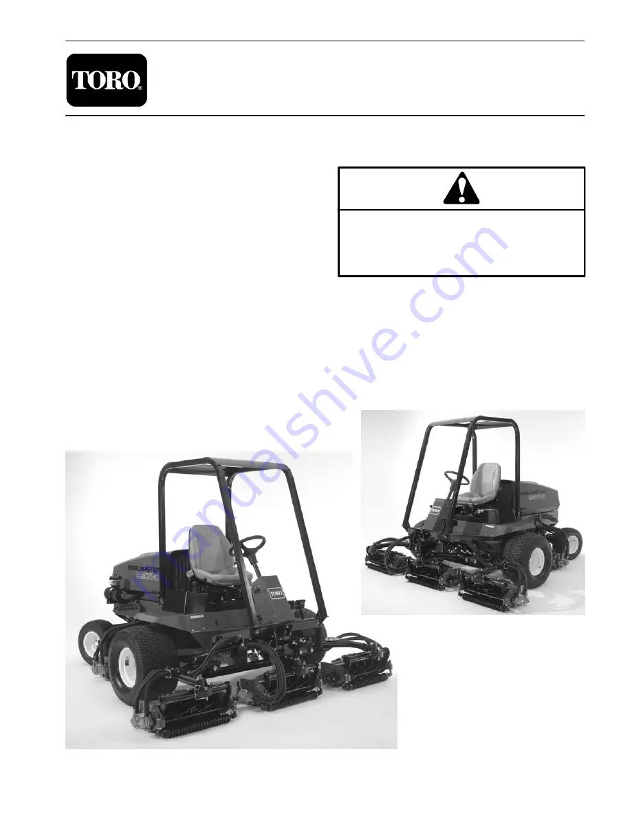
Reelmaster

 5500-D

Preface

The purpose of this publication is to provide the service
technician with information for troubleshooting, testing,
and repair of major systems and components on the
Reelmaster 5500-D.

REFER TO THE TRACTION UNIT AND CUTTING
UNIT OPERATOR’S MANUALS FOR OPERATING,
MAINTENANCE AND ADJUSTMENT INSTRUC-
TIONS. Space is provided in Chapter 2 of this book to
insert the Operator’s Manuals and Parts Catalogs for
your machine. Replacement Operator’s Manuals are
available by sending complete Model and Serial Num-
ber to:

The Toro Company
8111 Lyndale Avenue South
Bloomington, MN  55420–1196

The Toro Company reserves the right to change product
specifications or this publication without notice.

This safety symbol means DANGER, WARNING,
or CAUTION, PERSONAL SAFETY INSTRUC-
TION. When you see this symbol, carefully read
the instructions that follow. Failure to obey the
instructions may result in personal injury.

NOTE: NOTE will give general information about the
correct operation, maintenance, service, testing, or re-
pair of the machine.

IMPORTANT: The IMPORTANT notice will give im-
portant instructions which must be followed to pre-
vent damage to systems or components on the
machine.

 The Toro Company – 2000, 2002, 2003, 2004, 2007

Summary of Contents for 00075SL

Page 1: ...complete Model and Serial Num ber to The Toro Company 8111 Lyndale Avenue South Bloomington MN 55420 1196 The Toro Company reserves the right to change product specifications or this publication without notice This safety symbol means DANGER WARNING or CAUTION PERSONAL SAFETY INSTRUC TION When you see this symbol carefully read the instructions that follow Failure to obey the instructions may resu...

Page 2: ...Reelmaster 5500 D ...

Page 3: ...SERIES DIESEL ENGINE Chapter 4 Hydraulic System Specifications 4 2 General Information 4 3 Hydraulic Schematics 4 8 Hydraulic Flow Diagrams 4 12 Special Tools 4 22 Troubleshooting 4 24 Testing 4 27 Adjustments 4 37 Service and Repairs 4 41 Chapter 5 Electrical System Electrical Schematics and Electrical Harness and Con nectors Drawings 5 2 Special Tools 5 3 Troubleshooting 5 5 Electrical System Qu...

Page 4: ...Reelmaster 5500 D ...

Page 5: ...shooting 8 5 Initial Set up and Adjustments 8 7 Daily Adjustments 8 16 Service and Repairs 8 16 Chapter 8 1 Groomer Troubleshooting 8 1 2 Adjustments 8 1 4 Service and Repairs 8 1 5 Chapter 9 4WD Rear Axle Specifications 9 2 General Information 9 3 Adjustments 9 4 Repairs 9 5 Chapter 10 Electrical Diagrams Electrical Schematics 10 3 Electrical Harness Drawings 10 5 ...

Page 6: ...Reelmaster 5500 D ...

Page 7: ...ildren to operate the machine Do not allow adults to operate machine without proper instruc tion Only trained operators who have read this manual should operate this machine 3 Never operate the machine when under the influ ence of drugs or alcohol 4 Keep all shields safety devices and decals in place If a shield safety device or decal is defective illegible or damaged repair or replace it before o...

Page 8: ...st be skilled and trained in how to drive on hillsides Failure to use caution on slopes or hills may cause loss of control and vehicle to tip or roll possibly re sulting in personal injury or death On 4 wheel drive models always use the seat belt and ROPS together 17 If engine stalls or loses power and cannot make it to the top of a slope do not turn machine around Always back slowly straight down...

Page 9: ...form maintenance or an adjustment keep hands feet clothing and other parts of the body away from cutting units and other mov ing parts Keep everyone away 30 Do not overspeed the engine by changing governor setting To assure safety and accuracy have an Autho rized Toro Distributor check maximum engine speed 31 Shut engine off before checking or adding oil to the crankcase 32 Disconnect battery befo...

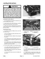
Page 10: ...e preferred method of lifting the rear end of the machine is Fig 2 A Secure a chain fall or hoist to the tie down rod on the rear of the frame B Chock both front tires Lift rear of the machine off the ground C On 2WD models use jack stands or blocks under the axle as close to the wheels as possible to secure the machine D On 4WD models use jack stands or blocks under the axle tube as close to the ...

Page 11: ... for Dry Zinc Plated and Steel Fasteners Metric Fasteners 5 Other Torque Specifications 6 Product Records Insert Operator s Manual and Parts Catalog for your Reelmaster 5500 D at the end of this chapter Addition ally if any optional equipment or accessories have been installed to your machine insert the Installation Instruc tions Operator s Manuals and Parts Catalogs for those options at the end o...

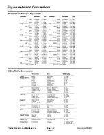
Page 12: ...0 09375 Rev D Reelmaster 5500 D Page 2 2 Product Records and Maintenance Equivalents and Conversions ...

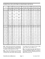
Page 13: ...er presence of a prevailing torque feature hard ness of the surface underneath the fastener s head or similar condition which affects the installation As noted in the following tables torque values should be reduced by 25 for lubricated fasteners to achieve the similar stress as a dry fastener Torque values may also have to be reduced when the fastener is threaded into aluminum or brass The specif...

Page 14: ... 2 22 3 30 3 41 4 43 4 58 5 3 8 24 UNF 17 2 18 2 24 3 35 3 47 4 50 4 68 5 7 16 14 UNC 27 3 27 3 37 4 50 5 68 7 70 7 95 9 7 16 20 UNF 29 3 29 3 39 4 55 5 75 7 77 7 104 9 1 2 13 UNC 30 3 48 7 65 9 75 8 102 11 105 10 142 14 1 2 20 UNF 32 3 53 7 72 9 85 8 115 11 120 10 163 14 5 8 11 UNC 65 10 88 12 119 16 150 15 203 20 210 20 285 27 5 8 18 UNF 75 10 95 15 129 20 170 15 230 20 240 20 325 27 3 4 10 UNC ...

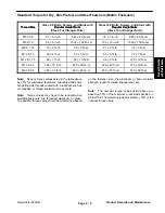
Page 15: ...b 72 7 N m M12 X 1 75 66 7 ft lb 90 10 N m 92 9 ft lb 125 12 N m M16 X 2 0 166 15 ft lb 225 20 N m 229 22 ft lb 310 30 N m M20 X 2 5 325 33 ft lb 440 45 N m 450 37 ft lb 610 50 N m Note Reduce torque values listed in the table above by 25 for lubricated fasteners Lubricated fasteners are defined as threads coated with a lubricant such as oil graphite or thread sealant such as Loctite Note Torque v...

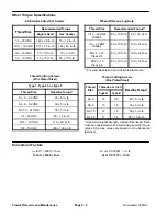
Page 16: ...in lb Wheel Bolts and Lug Nuts Thread Size Recommended Torque 7 16 20 UNF Grade 5 65 10 ft lb 88 14 N m 1 2 20 UNF Grade 5 80 10 ft lb 108 14 N m M12 X 1 25 Class 8 8 80 10 ft lb 108 14 N m M12 X 1 5 Class 8 8 80 10 ft lb 108 14 N m For steel wheels and non lubricated fasteners Thread Cutting Screws Zinc Plated Steel Thread Size Threads per Inch Baseline Torque Size Type A Type B Baseline Torque N...

Page 17: ... Injectors 9 Change Engine Oil and Filter 9 Clean Radiator and Oil Coolers 10 Replace Fuel Filter 10 Muffler Removal and Installation 11 Fuel System 12 Check Fuel Lines and Connections 12 Fuel Tank Removal 13 Drain and Clean Fuel Tank 13 Fuel Tank Installation 13 Air Filtering System 14 General Maintenance 14 Service Precleaner Bowl 14 Service Air Cleaner 14 Water Fuel Separator 15 Draining 15 Fil...

Page 18: ...ice shops Special tools are described in the Kubota Workshop Manual Diesel Engine 05 Series The use of some specialized test equipment is explained However the cost of the test equipment and the specialized nature of some re pairs may dictate that the work be done at an engine re pair facility Service and repair parts for Kubota engines are sup plied through your Authorized Toro Distributor If no ...

Page 19: ...uel ASTM D975 Fuel Capacity liters U S gallons 37 9 10 0 Fuel Injection Pump Bosch MD Type Mini Pump Governor Centrifugal Mechanical Low Idle no load 1150 50 150 RPM High Idle no load 3200 50 150 RPM Direction of Rotation Counterclockwise Viewed from Flywheel Compression Ratio 23 0 1 Injection Nozzles Mini Nozzle DNOPD Engine Oil 10W30 Detergent API CD or higher Oil Pump Trochoid Type Crankcase Oi...

Page 20: ...ill Fuel Tank DANGER Because diesel fuel is highly flammable use cau tion when storing or handling it Do not smoke while filling the fuel tank Do not fill fuel tank while engine is running hot or when machine is in an enclosed area Always fill fuel tank outside and wipe up any spilled diesel fuel before start ing the engine Store fuel in a clean safety ap proved container and keep cap in place Use...

Page 21: ...e extremely dusty or dirty see Engine Cooling System 1 Park machine on a level surface lower cutting units stop engine engage parking brake and remove key from the ignition switch CAUTION If engine has been running pressurized hot cool ant can escape when the radiator cap is removed and cause burns Open radiator cap only when the radiator and engine are cold Figure 3 1 Expansion tank 2 Cap 1 2 2 C...

Page 22: ...n the control lever arm Note Do not over tighten the cable connector The connector must be free to swivel 4 Hold fuel injection pump lever arm against the high idle stop screw and tighten the cable connector 5 Torque lock nut used to set the friction device on the throttle lever from 40 to 55 in lb 4 5 to 6 2 N m The maximum force required to operate the throttle lever should be 20 lb 89 N Figure ...

Page 23: ...ust ment is necessary proceed to the next step 3 Loosen bolts securing alternator to support bracket and to engine 4 Gently pry alternator away from engine 5 When proper tension is achieved tighten alternator bolts Cooling Fan Belt Fig 7 6 Loosen upper and lower lock nuts on the belt ten sioner lever IMPORTANT Make sure both lock nuts are loosen before setting cooling fan belt tension Not loosen i...

Page 24: ...gine only not for any other pur pose 3 Loosen air bleed screw on the top of the fuel filter wa ter separator Fig 8 4 Pump lever on the fuel pump Fig 9 until a solid stream of fuel flows out around the bleed screw on the fuel filter water separator Tighten air bleed screw 5 Open air bleed screw on the fuel injection pump with a 12 mm wrench Fig 10 6 Pump lever on fuel pump Fig 9 until a solid strea...

Page 25: ...osen pipe connection to the No 1 injector nozzle and holder assembly Figure 11 1 No 1 injector nozzle 2 No 2 injector 3 No 3 injector nozzle 3 2 1 3 Move throttle to FAST position 4 Turn ignition switch to START and watch fuel flow around connector Turn key to OFF when solid flow is observed Tighten pipe connector securely to the injec tor nozzle 5 Repeat steps on the remaining injector nozzles Ch...

Page 26: ...aise oil coolers and pivot forward Clean both sides of oil coolers and radiator area thoroughly with compressed air Reinstall oil coolers 6 Reinstall screen and close hood Figure 14 1 Screen 2 Latch 2 1 2 Figure 15 1 Transmission oil cooler 2 Reel oil cooler 3 Radiator 3 1 2 Replace Fuel Filter Replace fuel prefilter periodically as recommended in the maintenance schedules in Chapter 2 Product Re ...

Page 27: ...0 12 20 21 Muffler Removal CAUTION The muffler and exhaust pipe may be hot To avoid possible burns allow the engine and ex haust system to cool before working on the muf fler 1 Park machine on a level surface lower cutting units stop engine engage parking brake and remove key from the ignition switch 2 Remove muffler and or muffler bracket from the en gine as necessary using Figure 17 as a guide M...

Page 28: ...20 35 Never Seez 30 to 60 in lb 3 4 to 6 8 N m DANGER Because diesel fuel is highly flammable use cau tion when storing or handling it Do not smoke while filling the fuel tank Do not fill fuel tank while engine is running hot or when machine is in an enclosed area Always fill fuel tank outside and wipe up any spilled diesel fuel before start ing the engine Store fuel in a clean safety ap proved co...

Page 29: ...l tank if the fuel system becomes contaminated or if the ma chine is to be stored for an extended period 1 Remove fuel tank from the machine see Fuel Tank Removal 2 Flush fuel tank out with clean diesel fuel and com pletely drain Make sure tank is free of contaminates and debris 3 Install fuel tank to the machine see Fuel Tank Instal lation Fuel Tank Installation Fig 18 1 Install fuel tank to the ...

Page 30: ...an inside of the air cleaner cover 2 Carefully slide filter element out of the air cleaner body to prevent dislodging dust Replace the filter ele ment if damaged The filter element may be washed or blown clean using the following procedures Washing Method A Prepare a solution of filter cleaner and water Soak filter element about 15 minutes Follow direc tions on the cleaner carton B Rinse filter wi...

Page 31: ...om of the separator base 4 Allow all water and contaminants to drain from the separator Tighten drain valve Filter Element Replacement 1 Park machine on a level surface lower cutting units stop engine engage parking brake and remove key from the ignition switch 2 Clean area where filter element mates with base and filter head 3 Place a suitable container under fuel water separa tor and unscrew fil...

Page 32: ...oud 26 Radiator drain 27 Driveline hoop 28 Flat washer 29 Capscrew 30 Hose clamp 31 Lower radiator hose 32 Radiator 33 Radiator shield 34 Grommet 35 Grommet 36 Starter relay 37 Capscrew 38 Flat washer 39 Lock washer 40 Capscrew 41 Oil cooler hook 42 Pop rivet 43 Fuel vent hose 44 Hose clamp 45 Tube clamp 46 Hydraulic hose 47 O ring 48 Straight Hydraulic fitting 49 Transmission oil heat exchanger 5...

Page 33: ...ower radiator shield Disconnect any fuel lines that pass through the lower radiator shield DANGER Because diesel fuel is highly flammable use cau tion when storing or handling it Do not smoke while servicing fuel lines 8 Remove four cap screws flat washers and lock washers securing the radiator support to the frame Pull radiator and support from the frame 9 Plug any openings to prevent contaminati...

Page 34: ...H 40 Engine mounting bracket RH 41 Engine fan support 42 Fan idler bracket 43 Lock washer 44 V belt 45 Cap screw 46 Idler pulley 47 Throttle mounting bracket 48 Fan support bracket 49 Flat washer 50 Lock washer 51 Cable clamp 52 Toothed lock washer 53 Cap screw 54 Fan mounting plate 55 Flange screw 56 Lock nut 57 Fan mounting bracket 58 Rear engine bracket LH 59 Front engine bracket 60 Cap screw 6...

Page 35: ...6 Disconnect air filter hose from the engine 7 Disconnect wires and or electrical connections from the following electrical components A The oil low pressure switch starter and alterna tor Fig 26 The temperature sender Fig 27 B Battery frame and wire harness ground to the engine block and the ETR solenoid Fig 28 C High temperature shutdown switch Fig 29 Glow plug bus Fig 30 8 Disconnect fuel hose ...

Page 36: ...nstallation 3 Connect hoist or lift to the front and rear lift tabs CAUTION One person should operate lift or hoist while the other person guides the engine into the machine IMPORTANT Make sure not to damage the engine radiator fuel and hydraulic lines electrical harness or other parts while installing the engine 4 Position fan shroud around the engine fan Position engine slowly into the machine N...

Page 37: ...ck Make sure radiator drain is shut Fill radiator with coolant see Check Coolant System 12 Secure yoke flange to the lower fan belt pulley with three socket head screws and lock washers Fig 25 A Apply Loctite 242 or equivalent to the threads of the screws B Torque screws from 30 to 35 ft lb 41 to 47 N m C Lubricate yoke slip tube see Lubrication in Chap ter 2 Product Records and Maintenance 13 Con...

Page 38: ...Place bearing spacer into fan drive hub 3 Pressing equally on both inner and outer races of second bearing install second bearing until it contacts shoulder in hub Make sure that bearing spacer bore is aligned with bearing bores 4 While supporting inner bearing race press pulley into bearing bores 5 Apply Loctite 242 or equivalent to threads of shaft screw Install flat washer and shaft screw Torqu...

Page 39: ...action Control Linkage 40 SERVICE AND REPAIRS 41 General Precautions for Removing and Installing Hydraulic System Components 41 Check Hydraulic Lines and Hoses 42 Flush Hydraulic System 42 Charge Hydraulic System 43 Change Hydraulic Fluid 44 Replace Hydraulic Oil Filter 45 Replace Transmission Fluid 46 Replace Transmission Filter 46 Transmission Control Linkage 47 Transmission 48 Transmission Serv...

Page 40: ...displacement gear type pumps Maximum Operating Pressure 3000 PSI 207 bar Steering Relief Pressure 1450 PSI 100 bar Hydraulic Manifold Reel Front Reels Circuit Relief Pressure R1 3000 PSI 207 bar Rear Reels Circuit Relief Pressure R2 2000 PSI 138 bar Reel Motors Gear motor Maximum Operating Pressure 3000 PSI 207 bar Hydraulic Filter Reels Lift and Steering Circuits Spin on cartridge type with 50 ps...

Page 41: ...rch for leaks Hydraulic fluid escaping under pressure can have sufficient force to penetrate the skin and cause serious injury If fluid is injected into the skin it must be surgi cally removed within a few hours by a doctor familiar with this type of injury Gangrene may result from such an injury Hydraulic Fitting Installation O Ring Face Seal 1 Make sure both threads and sealing surfaces are free...

Page 42: ...e of burrs nicks scratches or any foreign material 2 Always replace the O ring seal when this type of fit ting shows signs of leakage 3 Lubricate the O ring with a light coating of oil 4 Turn back the jam nut as far as possible Make sure the back up washer is not loose and is pushed up as far as possible Step 1 5 Install the fitting into the port and tighten finger tight until the washer contacts ...

Page 43: ...ive shaft to the engine drive coupler Loosen capscrews clamping drive shaft to transmission Fig 6 Remove drive shaft 2 Attach a suitable chain strap or cable to the center of the front frame member Fig 7 IMPORTANT Lock both brake pedals together be fore towing 3 Attach the other end of the towing device to a vehicle that is capable of towing the machine safely and at speeds below 3 mph 4 An operat...

Page 44: ...ller neck and wipe it with a clean rag Insert dipstick into filler neck then remove it and check level of fluid Fluid level should be within 1 4 inch 0 6 cm of the mark on dipstick 4 If level is low add appropriate fluid to raise level to full mark 5 Install dipstick and cap onto filler neck IMPORTANT Two groups of hydraulic fluid are spe cified to allow optimal operation of the machine in a wide ...

Page 45: ...3 BP Oil Energol HLP68 Castrol Hyspin AWS68 Chevron Chevron EP68 Citgo Citgo A W68 Conoco Super Hydraulic Oil 31 Exxon Nuto H68 Gulf 68AW Pennzoil lAW Hyd Oil 68 Phillips Magnus A315 Standard Industron 53 Texaco Rando HD68 Union Unax AW 315 Group 3 Hydraulic Fluid Biodegradable ISO VG 32 46 anti wear hydraulic fluid Mobil EAL 224 H Note This biodegradable hydraulic fluid in this group is not compa...

Page 46: ...SSURE 150 PSI 3625 PSI 70 PSI 2755 PSI 70 PSI OIL FILTER SYSTEM RELIEF SYSTEM RELIEF COOLER BY PASS FILTER BY PASS CHARGE PRESSURE RELIEF HEAT EXCHANGER IN LINE STRAINER DIFFERENTIAL HOUSING INPUT SHAFT OUTPUT SHAFT Hydraulic Transmission Schematic Reelmaster 5500 D SYSTEM PRESSURE FORWARD REVERSE ...

Page 47: ...LP1 MOW1 LC2 OR2 025 DIA 025 DIA LC1 FC1 OR1 MOW MSV2 MSV1 R2 2000 PSI R1 T P1 3000 MOW CIRCUIT C U 2 G3 4 SV5 C5 C6 SV4 C4 PT CD3 CD2 T 1 5 C3 SV3 C2 SV2 C1 ST SV1 P3 100MESH SUCTION STRAINER M4 R9 R9 M1 R9 R9 M5 R9 R9 R9 R9 M2 R9 R9 M3 R3 COOLER FILTER PSI 1450 R10 50 PSI 3 2 RAISE LOWER C2 C1 P FD1 FLOW DIVIDER FLOW DIVIDER SERIAL NUMBER ABOVE 210000400 Serial Number Below 220000000 STEERING CO...

Page 48: ...em Rev C Page 4 10 Hydraulic System Schematic Reelmaster 5500 D All solenoids are shown as de energized Serial Number Above 220000000 STEERING CONTROL VALVE REEL CONTROL MANIFOLD LIFT CONTROL MANIFOLD 2000 PSI 3000 PSI 50 PSI 1450 PSI ...

Page 49: ...Hydraulic System Reelmaster 5500 D Hydraulic System Rev C Page 4 11 This page is intentionally blank ...

Page 50: ...M RELIEF SYSTEM RELIEF COOLER BY PASS FILTER BY PASS CHARGE PRESSURE RELIEF HEAT EXCHANGER IN LINE STRAINER DIFFERENTIAL HOUSING INPUT SHAFT OUTPUT SHAFT Traction Circuit Forward Direction Shown High Pressure Low Pressure Charge Return or Suction Flow Reelmaster 5500 D SYSTEM PRESSURE CHARGE PRESSURE SYSTEM PRESSURE FORWARD REVERSE ...

Page 51: ...ystem pressure is limited by a high pressure relief valve on each side of the closed loop circuit System pressure can be measured at test ports on the transmission If pressure exceeds the relief setting oil flows through the relief valve to the low pressure side of the closed loop circuit An integral charge pump provides a constant supply of charge oil to the variable displacement pump and closed ...

Page 52: ... IN OUT AUX G1 G2 C U 3 MD2 MOW2 BKLP2 BACKLAP FC2 PSI P2 C U 5 C U 1 MOW CIRCUIT C U 4 BACKLAP MOW MD1 BKLP1 MOW1 LC2 OR2 025 DIA 025 DIA LC1 FC1 OR1 MOW MSV2 MSV1 R2 2000 PSI R1 T P1 3000 MOW CIRCUIT C U 2 G3 4 SV5 C5 C6 SV4 C4 PT CD3 CD2 T 1 5 C3 SV3 C2 SV2 C1 ST SV1 P3 100MESH SUCTION STRAINER M4 R9 R9 M1 R9 R9 M5 R9 R9 R9 R9 M2 R9 R9 M3 R3 COOLER FILTER PSI 1450 R10 50 PSI 3 2 RAISE LOWER FLO...

Page 53: ...raulic reservoir To lower the cutting units solenoid valves SV3 SV4 and SV5 energize along with solenoid valve SV1 So lenoid valve SV2 is in its normally de energized posi tion and directs oil flow to the piston end of the lift cylinders Hydraulic pressure against the piston side of the cylinder causes the shafts to extend and lower the cutting units When the solenoids are deenergized the lift cyl...

Page 54: ...V1 IN OUT AUX G1 G2 C U 3 MD2 MOW2 BKLP2 BACKLAP FC2 PSI P2 C U 5 C U 1 MOW CIRCUIT C U 4 BACKLAP MOW MD1 BKLP1 MOW1 LC2 OR2 025 DIA 025 DIA LC1 FC1 OR1 MOW MSV2 MSV1 R2 2000 PSI R1 T P1 3000 MOW CIRCUIT C U 2 G3 4 SV5 C5 C6 SV4 C4 PT CD3 CD2 T 1 5 C3 SV3 C2 SV2 C1 ST SV1 P3 100MESH SUCTION STRAINER M4 R9 R9 M1 R9 R9 M5 R9 R9 R9 R9 M2 R9 R9 M3 R3 COOLER FILTER PSI 1450 R10 50 PSI 3 2 RAISE LOWER F...

Page 55: ...rol valve and into the lift manifold All lift manifold so lenoid valves are de energized and flow is directed to the hydraulic reservoir To raise the cutting units solenoid valves SV3 SV4 and SV5 energize along with solenoid valve SV1 So lenoid valve SV2 is also energized and directs oil flow to the rod end of the lift cylinders Hydraulic pressure against the rod side of the cylinder causes the sh...

Page 56: ...T AUX G1 G2 C U 3 MD2 MOW2 BKLP2 BACKLAP FC2 PSI P2 C U 5 C U 1 MOW CIRCUIT C U 4 BACKLAP MOW MD1 BKLP1 MOW1 LC2 OR2 025 DIA 025 DIA LC1 FC1 OR1 MOW MSV2 MSV1 R2 2000 PSI R1 T P1 3000 MOW CIRCUIT C U 2 G3 4 SV5 C5 C6 SV4 C4 PT CD3 CD2 T 1 5 C3 SV3 C2 SV2 C1 ST SV1 P3 100MESH SUCTION STRAINER M4 R9 R9 M1 R9 R9 M5 R9 R9 R9 R9 M2 R9 R9 M3 R3 COOLER FILTER PSI 1450 R10 50 PSI 3 2 RAISE LOWER FLOW DIVI...

Page 57: ... MD1 is in the Mow position the front reels rotate correctly for mowing Return oil from the motors is also directed to the reservoir through valve MD1 System pressure on the P1 side can be measured at Port G1 On the circuit supplied by pump section P2 maximum system pressure is limited by relief valve R2 which is set at 2000 PSI Solenoid valve MS2 must be ener gized to prevent hydraulic flow from ...

Page 58: ...G CONTROL VALVE LEFT TURN FROM P3 TO LIFT MANIFOLD V1 STEERING CYLINDER AUX IN OUT LH RH STEERING CONTROL VALVE RIGHT TURN FROM P3 TO LIFT MANIFOLD V1 P3 P1 P2 RH LH V1 IN OUT AUX P2 T P1 G3 4 SV5 C5 C6 SV4 C4 PT CD3 CD2 T 1 5 C3 SV3 C2 SV2 C1 ST SV1 P3 100MESH SUCTION STRAINER R3 COOLER FILTER STEERING CONTROL VALVE NEUTRAL STRAIGHT AHEAD PSI 1450 R10 50 PSI 3 2 RAISE LOWER FLOW DIVIDER ...

Page 59: ...o the rod end of the steering cylinder The rotary meter ensures that the oil flow to the cylinder is proportional to the amount of steering wheel rotation The steering cylinder retracts pivoting the rear wheels to the left This results in a turn to the operator s right when the vehicle is moving forward Fluid leaving the steering cylinder flows back through the steering control valve exits through...

Page 60: ...e seal ORFS adapter fit tings for use on this machine 1 INLET HOSE Hose connected from the system cir cuit to the inlet side of the hydraulic tester 2 LOAD VALVE A simulated working load is created in the circuit by turning the valve to restrict flow 3 LOW PRESSURE GAUGE Low range gauge to pro vide accurate reading at low pressure 0 to 1000 PSI A protector valve cuts out when pressure is about to ...

Page 61: ...tem The kit includes tee s unions reducers plugs caps and male test fittings Figure 12 Measuring Container TOR4077 Use this container for doing hydraulic motor efficiency testing motors with case drain lines only Measure effi ciency of a hydraulic motor by restricting the outlet flow from the motor and measuring leakage from the case drain line while the motor is pressurized by the hydraulic syste...

Page 62: ... is faulty Charge check valve and or system relief valve is faulty Machine travels too far before stop ping when the traction pedal is re leased Traction linkage is out of adjustment Traction pedal does not return to neutral restriction Transmission operates hot Engine RPM is too low Transmission reservoir oil level is too low Cooling system is not operating properly Oil cooler bypass relief valve...

Page 63: ...ront Rear reels stop under load Relief valve R1 R2 is by passing Reel motor has internal leakage by passing oil Gear pump section P1 P2 is inefficient Cutting units will not raise Engine RPM is too low Solenoid valve SV2 is not shifting Solenoid valve SV1 is not shifting Solenoid valve SV3 SV4 or SV5 is not shifting Relief valve R3 is by passing Lift cylinder s has have internal leakage Lift arm p...

Page 64: ...Reelmaster 5500 D Hydraulic System Rev C Page 4 26 This page is intentionally blank ...

Page 65: ...s use paper or cardboard Hydraulic fluid escaping under pressure can have sufficient force to penetrate the skin and cause serious injury If fluid is injected into the skin it must be surgically removed within a few hours by a doctor familiar with this type of injury Gan grene may result from such an injury 1 Clean machine thoroughly before disconnecting or disassembling any hydraulic components A...

Page 66: ...5 If there is no pressure or pressure is low check for restriction in pump intake line Inspect charge relief valve and valve seat Charge pressure can be adjusted by changing shim thickness behind the spring Check for sheared charge pump key Disassemble charge pump and check for internal damage or worn parts 6 Also take a gauge reading while operating the ma chine in forward and reverse Start the e...

Page 67: ...nning of this section Note Test ports are 7 16 20 SAE O ring ports 3 Connect a 5 000 psi 350 Bar gauge to traction cir cuit test port for function to be checked Fig 15 4 Start the engine and move throttle to full speed 3200 RPM 5 Sit on seat and with brakes engaged slowly de press the top of traction pedal While pushing top of trac tion pedal down look at pressure reading on gauge GAUGE READING Fo...

Page 68: ... in series with the hose and hydraulic fitting on reel motor Make sure the flow control valve on tester is fully open 6 Start engine and move throttle to full speed 3200 RPM WARNING Keep away from reels during test to prevent per sonal injury from rotating reel blades 7 Have another person occupy seat move Enable Disable switch to ENABLE Move Lower Mow Raise lever forward to engage cutting units t...

Page 69: ... tween pressure hose and reel manifold block fitting Fig 18 or between pressure hose and pump fitting Fig 19 for suspected bad pump section Make sure the tester flow control valve is OPEN Front circuit port P1 rear pump section shaft end Rear circuit port P2 center pump section IMPORTANT Make sure that the oil flow indicator arrow on the flow gauge is showing that the oil will flow from the pump t...

Page 70: ...R9 R9 M1 R9 R9 M5 R9 R9 Figure 20 Note One way to find a bad reel motor is to have another person observe the machine while mowing in dense turf A bad motor will run slower produce fewer clippings and may cause marcelling or a washboard appearance on the turf 1 Make sure hydraulic oil is at normal operating temper ature before doing test CAUTION Keep away from reels during tests to prevent persona...

Page 71: ...ow Backlap valve is in the Mow position 6 With cutting units in lowered position and engine OFF insert a block of wood between cutting unit reel blades and front cross tube of cutting unit to prevent reel from turning Fig 20 7 One person should sit on the seat and operate the machine while another person reads the tester Start the engine and move Enable Disable switch to ENABLE Move Lower Mow Rais...

Page 72: ...Note Over a period of time a reel motor can wear in ternally A worn motor may by pass oil to its case drain causing the motor to be less efficient Eventually enough oil loss will cause the reel motor to stall under heavy cutting conditions continued operation with a worn inefficient motor can generate a lot of heat cause damage to seals and other components in the hydraulic system and affect quali...

Page 73: ...lve on tester is fully open Fig 21 6 Set reel speed control to the full speed position Make sure Mow Backlap valve is in the Mow position Note Use a graduated container special tool TOR4077 to measure case drain leakage Fig 21 CAUTION Cutting unit reels will rotate when lowered with Enable Disable switch in ENABLE position Keep away from cutting units during test to pre vent personal injury from r...

Page 74: ...flow is completely restricted or stopped damage to the pump tester or other com ponents could occur 4 Make sure the parking brake is engaged Start the engine and move throttle to full speed 3000 RPM DO NOT engage the cutting units 5 While watching pressure gauges slowly close flow control valve until 1000 PSI 69 bar is obtained on gauge Verify pump speed at 3000 RPM at the transmis sion input shaf...

Page 75: ...may spray out of the valve with the cap off Personal injury may result Always install the cap and tighten before pressurizing the system Note Do not remove the relief valve from the hydrau lic manifold for adjustment 1 Remove cap from the relief valve with an allen wrench Note A 1 8 turn of the adjustment socket is about 50 psi 3 5 bar or 1 turn is about 400 psi 27 6 bar 2 To increase pressure set...

Page 76: ... drive driveshaft must be removed 3 Under right side of machine loosen locknut on trac tion adjustment cam Fig 25 WARNING Engine must be running so final adjustment of the traction adjustment cam can be performed To guard against possible personal injury keep hands feet face and other parts of the body away from the muffler other hot parts of the engine and other rotating parts 1 Traction adjustme...

Page 77: ...ting Units Fig 26 1 Locate valve behind access panel above operator s platform 2 Loosen setscrew on valve and rotate valve approxi mately 1 2 turn clockwise 3 Verify drop rate adjustment by raising and lowering cutting units several times Readjust as required 4 After desired drop rate is attained tighten set screw to lock adjustment Rear Cutting Units Fig 27 1 Raise hood and locate valve in center...

Page 78: ...e 1 The machine should be parked on a level surface cutting units lowered to the floor and engine off 2 Connect brake pedals together with locking pin push both pedals down and pull parking brake latch out 3 Adjust inner locknut until distance between inside of eye bolt loop and inside of spring anchor plate is 2 75 70 mm Fig 28 Tighten outer locknut 4 Operate the machine and check for safe stoppi...

Page 79: ...ses for proper installation after repairs are completed 5 Note the position of hydraulic fittings especially el bow fittings on hydraulic components before removal Mark parts if necessary to make sure they will be aligned properly when reinstalling hydraulic hoses and tubes After Repair or Replacement of Components 1 Check oil level in the hydraulic reservoir and add cor rect oil if necessary Drai...

Page 80: ... around any hy draulic connections that will be disconnected for draining 2 Drain hydraulic reservoir see Change Hydraulic Fluid 3 Drain hydraulic system Drain all hoses tubes and components while the system is warm 4 Change and replace oil filter see Change Hydraulic Oil Filter 5 Inspect and clean hydraulic reservoir see Hydraulic Reservoir Inspection 6 Reconnect all hydraulic hoses lines and com...

Page 81: ... Raise one front and rear wheel off the floor and place support blocks under the frame Chock remaining wheel to prevent movement of the machine 10 Make sure traction pedal and lift control lever are in neutral Start engine and run it at low idle of 1150 rpm The charge pump should pick up oil and fill the hydraulic system If there is no indication of fill in 30 seconds stop the engine and determine...

Page 82: ... fluid flow into drain pan Fig 29 Reinstall and tighten plug when hydraulic fluid stops draining IMPORTANT Use only hydraulic fluids specified Other fluids could cause system damage 3 Fill reservoir with approximately 8 5 gallons 32 L of hydraulic fluid Refer to Checking Hydraulic Fluid 4 Install reservoir cap Fig 30 Start engine and use all hydraulic controls to distribute hydraulic fluid through...

Page 83: ...n unit Use of any other fil ter may void the warranty on some components 1 Position machine on a level surface lower the cut ting units stop the engine engage the parking brakes and remove key from ignition switch 2 Clean area around filter mounting area Place drain pan under filter and remove filter Fig 31 3 Lubricate new filter gasket and fill the filter with hy draulic fluid 4 Assure filter mou...

Page 84: ...fore the engine is started 1 Oil filter 2 Suction line 3 Hydraulic transmission Figure 32 4WD model shown 2 1 3 Replace Transmission Filter Change the transmission filter after the first 10 hours of operation and every 800 hours thereafter IMPORTANT Only the Toro replacement filter Part No 75 1330 can be used in the hydraulic system Use of any other filter may void the warranty on some components ...

Page 85: ... extension spring is under tension Loosen lock nut from eye bolt to relieve spring tension 3 Remove eyebolt from the spring anchor plate and extension spring from the switch arm Fig 33 4 Remove cotter pin and washer to disconnect traction control rod from pump control 5 Loosen cap screw and lock nut securing pump con trol to swashplate control shaft Note It is not necessary to disassemble transmis...

Page 86: ...ting 24 Test port cap 25 O ring 26 90o hydraulic fitting 27 Hose clamp 28 Hose 29 Cap screw 30 Hydraulic hose 31 Oil filter 32 Cap screw 33 Lock washer 34 Transmission 35 Lock nut 36 O ring 37 Pinion gear 38 Retaining ring 39 Transmission support 40 90o hydraulic fitting 41 In line strainer 42 45o hydraulic fitting 43 Axle shim 44 Flat washer 45 Lock nut 46 Front axle 47 Oil fill tube 48 Axle dip ...

Page 87: ... machine Fig 36 and 37 Note If the machine is going to be stored until trans mission is repaired or replaced cover hole in support plate with weatherproof tape to prevent contamination of the reservoir 9 Leave support plate installed and gear pump installed on the support plate 10 Remove retaining ring and remove pinion gear from transmission output shaft 11 Remove filter from the transmission Ins...

Page 88: ...ng Units 11 Install a new filter and fill differential with correct oil 12 Disconnect fuel stop solenoid electrical connector on engine to prevent engine from starting Prime transmis sion by turning ignition key switch to crank engine for 10 seconds Repeat cranking procedure again 13 Start the engine and let it idle for approximately two minutes Operate machine slowly in forward and re verse Stop ...

Page 89: ...Hydraulic System Reelmaster 5500 D Hydraulic System Rev C Page 4 51 This page is intentionally blank ...

Page 90: ...2 Spring 43 Spring 44 Plate valve 45 Motor shaft 46 Housing gasket 47 Pipe plug 48 Pin 49 Trunnion cover LH 50 Collar 51 Ball bearing 52 Check pressure relief valve reverse 53 Retaining ring Figure 38 31 32 33 34 35 36 37 38 39 40 41 42 43 44 45 46 47 48 49 50 51 52 53 1 2 3 4 5 6 7 8 9 10 16 17 18 19 20 21 43 22 36 25 26 27 28 29 30 11 12 13 14 15 19 21 19 6 9 26 21 27 20 21 22 22 20 21 23 The pr...

Page 91: ...ng Note position of longer and shorter screws The cylinder block springs will cause the center section to separate from the housing Fig 39 IMPORTANT The pump and motor cylinder blocks may stick to the valve plates and center section Be careful to prevent damage to the sealing surfaces 3 Remove center section from housing Fig 40 4 Remove gasket and two 2 alignment pins from housing IMPORTANT Be car...

Page 92: ...ntical To avoid mixing wear pat terns do not mix parts between pump and motor cylinder block assemblies Make sure each piston is returned to the bore it was taken from 8 Remove slipper guide and piston assemblies from cylinder blocks Fig 44 9 Use O ring pick or wire to remove thrust plates from swashplate and housing Fig 45 10 Use an internal hex wrench to remove pipe plug over motor shaft bearing...

Page 93: ...to remove motor shaft bearing retaining pin from housing Fig 47 12 Remove motor shaft from housing Fig 48 13 Press motor shaft out of the bearings and spacer Fig 49 14 Remove spiral retaining ring and remove PTO seal guide with O ring from the housing Fig 50 Figure 47 Figure 48 Figure 49 Figure 50 ...

Page 94: ...over and trunnion cover to housing Mark position of covers for reassembly The trunnion seal cover as sembly includes an O ring lip seal and trunnion bearing on the control side The trunnion cover assembly in cludes an O ring and trunnion bearing on the side oppo site the control Remove these parts from the housing Fig 52 17 Tilt and lift swashplate from housing Fig 53 Figure 51 Figure 52 Figure 53...

Page 95: ...TANT When installing the needle bearing the printed numbered end of the bearing cage must face the press pin 6 Install a new cylinder block kit if brass slippers on the pistons are scored or excessively rounded at edges Assembly Note During assembly of the transmission all sur faces which have relative motion between two parts should be coated with a film of clean hydraulic oil This will assure th...

Page 96: ... seal should be pressed flush with outer surface of seal cover Be careful not to dam age the seal Note Wrap end of swashplate control shaft with thin plastic to prevent damage to seal lip during installation 5 Install trunnion seal cover with O ring seal and trun nion bearing into housing and over swashplate trunnion see Trunnion Seal Replacement Fig 57 6 Install hex tapping screws and tighten to ...

Page 97: ...de and O ring into housing Install spiral retaining ring Fig 60 9 Press inner bearing spacer and outer bearing onto motor shaft Fig 61 10 Install motor shaft assembly into housing Fig 62 11 Install motor shaft bearing retaining pin into housing Fig 63 Figure 60 Figure 61 Figure 62 Figure 63 ...

Page 98: ...installing piston assemblies into the slipper guide Lubricate pistons and cylinder block bores Install assembled guide and pis tons into cylinder block by inserting pistons into cylinder block bores The pistons and bores are not selectively fitted so no specific piston and bore orientation is re quired Fig 66 15 Lay the transmission on its side and install cylinder block kits into the housing Fig ...

Page 99: ...ection with their bronze faces visible Fig 69 The notch on each valve plate must engage its locating pin Note Do not interchange pump and motor valve plates when assembling transmission The motor valve plate has grooves on both sides of the plate The pump plate has grooves on only one side of the plate Fig 70 19 Install the two 2 alignment pins and install a new center section gasket onto the hous...

Page 100: ...the center section to the housing and torque evenly to 33 to 41 ft lb 45 to 56 N m Fig 73 22 Rotate pump and motor shafts to make sure trans mission is assembled correctly When properly as sembled a maximum torque of 3 5 ft lb 4 7 N m should be required to turn either shaft 23 Assemble following components as described in the procedures Charge Pump Replacement In Line Filter Check Valve Replacemen...

Page 101: ...ore in charge pump cover Fig 75 4 Inspect the charge pump cover new seal and shaft for damage Inspect sealing area on shaft for rust wear or contamination Polish seal area on shaft if necessary 5 Use a seal installer tool or wrap spline end of shaft with thin plastic to prevent damage to seal lip during installation Lubricate inside diameter of new seal with petroleum jelly 6 Press new seal into c...

Page 102: ...rust wear or contamination Polish sealing area on shaft if necessary 7 Using an arbor press press seal into position from in side of seal cover until it bottoms out in its bore Be care ful not to damage the seal 8 Install O ring onto seal cover and retain with petro leum jelly 9 Use a seal installer tool or wrap end of swashplate control shaft with thin plastic to prevent damage to seal during ins...

Page 103: ...ght angle When re assembling install the check valve spring into the spe cial plug with its larger diameter toward the plug and snap the valve cartridge into position in the plug Note The forward and reverse valves are different The seating surface of the reverse check high pres sure relief valve has a machined groove in it Installing the reverse check high pressure relief valve in the wrong port ...

Page 104: ...spring and plug may remain inside the plug being held by an oil film Make sure the same number and thickness of shims is installed when reassembling the parts unless shims need to be added or removed to ad just the pressure setting 6 Reinstall the poppet spring and plug with shims and O ring into the housing Tighten the plug to a torque of 30 to 70 ft lb 41 to 95 N m 7 Before starting the engine c...

Page 105: ...ied by a yellow dye mark and requires a force of approximately 5 5 lb 24 5 N to compress it to a length of 1 280 inch 3 25 cm 5 Inspect the poppet and mating seat in the end cap for damage or foreign material 6 Reinstall the poppet spring and plug with O ring into the housing Tighten the plug to a torque of 30 to 70 ft lb 41 to 95 N m 7 Before starting the engine check the oil level in the differe...

Page 106: ...k the oil level again Check the transmission for leaks Filter Reverse Flow Check Valve Replacement 1 Park machine on a level surface lower cutting units stop engine engage parking brake and remove key from the ignition switch 2 Remove the filter reverse flow check valve hex plug Fig 81 3 Remove the spring and poppet from the housing 4 Do not interchange parts with another valve The spring used in ...

Page 107: ...press pin 8 Install the geroter drive pin in the groove in the drive shaft and retain with petroleum jelly 9 Before assembly lubricate the geroter assembly with clean hydraulic oil Install the geroter assembly into the charge pump cover Install the O ring and retain with petroleum jelly IMPORTANT Correct charge pump installation to match engine rotation is determined by the position of the charge ...

Page 108: ...ugs on open hydraulic lines and fittings Label dis connected hydraulic lines for proper Reassembly Fig 84 6 Remove two 2 cap screws and washers securing pump to support plate Remove pump transmission coupler and transmission adapter Installation 1 Lubricate a new O ring with clean hydraulic oil and install on pump 2 Install transmission coupler on the transmission out put shaft 3 Install pump shaf...

Page 109: ...Hydraulic System Reelmaster 5500 D Hydraulic System Rev C Page 4 71 This page is intentionally blank ...

Page 110: ...ler gear 11 Drive gear 12 Coupling 13 Bearing 14 Distance plate 15 Anti extrusion seal SNP2 16 Pressure loading seal SNP2 17 Housing 18 Idler gear 19 Drive gear 20 Housing 21 Idler gear 22 Drive gear 23 Relief valve 24 Valve block 25 Bolt Figure 85 1 2 3 7 8 9 10 11 12 13 21 25 24 23 22 5 4 14 17 15 20 5 Install with sharp edge facing out Install with sping side facing in 50 to 55 ft lb 68 to 75 N...

Page 111: ... cleaning solvent Make sure parts and work area are clean IMPORTANT Use caution when clamping in a vise to avoid distorting any parts 3 Secure the flange end of the pump in a vise with the drive shaft pointing down 4 Remove the four 4 pump housing bolts 5 Put your hand on the pump case and gently tap the pump case with a soft face hammer to loosen the pump sections Be careful not to drop parts or ...

Page 112: ...ce lower cutting units stop engine engage parking brake and remove key from the ignition switch 2 Disconnect hydraulic lines Put caps or plugs on fit tings and hoses to prevent contamination Tag hydraulic lines for proper reassembly 3 Loosen motor mounting nuts Fig 88 4 Rotate motor clockwise so motor flanges clear studs and pull motor out Installation 1 Place motor into position on mounting studs...

Page 113: ...e block Fig 87 7 Remove gear housing Make sure rear bearing block remains on drive and idler gear shafts 8 Remove rear bearing block from drive and idler gear shafts 9 Before removing gear set apply marking dye to mat ing teeth to retain timing Motor efficiency may be af fected if the teeth are not installed in the same position during reassembly 10 Remove idler gear 11 Remove drive gear and shaft...

Page 114: ...ully install gear housing over rear bearing block and slide gear housing down over the gears and front bearing block Make sure the markings put on the flange and housing earlier line up 8 The rear bearing block should sit just below back face of gear housing If bearing block sits higher that rear face of housing remove gear housing and check that E seal or O ring did not shift out of place during ...

Page 115: ...Hydraulic System Reelmaster 5500 D Hydraulic System Rev C Page 4 77 This page is intentionally blank ...

Page 116: ...8 19 19 32 23 25 26 29 28 28 19 20 21 30 Reel Manifold Removal Note The ports on the manifold are marked for easy identification of components Example R1 is the reel cir cuit relief valve and P1 is a gear pump connection port See Hydraulic Schematics to identify the function of the hydraulic lines and cartridge valves at each port Note Read the General Precautions for Removing and Installing Hydra...

Page 117: ...1 21 24 11 12 13 22 27 5 8 20 33 36 35 34 14 15 16 17 18 19 18 32 23 25 26 29 37 28 19 20 40 30 4 7 26 31 29 30 31 15 17 16 15 16 17 38 15 16 17 39 41 18 19 20 9 10 23 19 18 20 Lift Manifold Removal Note The ports on the manifold are marked for easy identification of components Example R1 is the reel cir cuit relief valve and P1 is a gear pump connection port See Hydraulic Schematics to identify t...

Page 118: ...30 Knob 31 Locating plate 32 Indicator plate 33 Jam nut 34 Detent plate 35 Detent spring 36 Detent ball 37 Set screw Figure 91 Reel Manifold 1 2 3 4 6 7 30 9 10 15 16 18 19 28 21 24 25 26 11 12 13 17 22 27 5 8 31 14 38 20 32 33 34 Loctite 242 45 ft lb 61 N m 2 to 5 ft lb 2 7 to 6 8 N m 10 7 3 23 29 36 35 37 MD1 MD2 R1 R2 FC1 FC2 MS1 MS2 P1 P2 G1 LC1 Reel Speed 61 N m 55 to 60 ft lb 75 to 81 N m 45...

Page 119: ...ing 15 Solenoid 20 watt Figure 92 Lift Manifold 4 6 7 9 10 11 12 5 8 3 Loctite 242 45 ft lb 61 N m 2 to 5 ft lb 2 7 to 6 8 N m 1 2 5 13 14 15 SV4 SV5 SV3 SV2 SV1 P1 15 Note The ports on the manifold s are marked for easy identification of components Example R1 is the reel circuit relief valve and P1 is the gear pump connec tion port See Hydraulic Schematics to identify the func tion of the hydraul...

Page 120: ...e as talcum powder can affect the operation of high pressure hydraulic valves Remove solenoid 7 Reinstall the cartridge valve A Lubricate new O rings and backup rings of seal kit with clean hydraulic oil and install The O ring and backup ring must be arranged properly on the car tridge valve for proper operation and sealing B Thread spool valve carefully into port The valve should go in easily wit...

Page 121: ...eed size 10 and 4 way directional control backlap size 12 Installa tion torque vales are different for each type A Lubricate new O ring and backup ring of seal kit with clean hydraulic oil and install The O ring and backup ring of seal kit must be arranged properly on the cartridge valve for proper operation and sealing B Thread cartridge valve carefully into the manifold port The valve should go ...

Page 122: ...ome lodged in small valve orifices or seal areas causing malfunction B If sealing surfaces appear pitted or damaged the hydraulic system may be overheating or there may be water in the system CAUTION Use eye protection such as goggles when using compressed air 4 Clean logic cartridge valve using clean mineral spir its Submerge valve in clean mineral spirits to flush out contamination Particles as ...

Page 123: ...three 3 port manifold and a flow divider cartridge The flow divider on later production machines includes a solenoid cartridge valve and two 2 flow regulator car tridges Fig 94 If necessary the cartridges can be carefully removed from the manifold for cleaning 1 Flow divider 2 O ring 3 Hydraulic fitting 4 O ring 5 Hydraulic hose 6 Cap screw 2 used 7 Flat washer 2 used 8 Hydraulic fitting 9 Hydraul...

Page 124: ...der pin and carrier frame Pull cylinder pin from carrier frame and cylinder clevis 5 Remove rear lift cylinder Fig 98 A Remove retaining ring from the cylinder rod end pin Remove cylinder pin with remaining retaining ring and thrust washers from the lift arm and cylinder clevis B Remove retaining ring from the cylinder cap end pin Remove cylinder pin with remaining retaining ring from the frame an...

Page 125: ...rust washer and retaining ring to the cylinder rod end pin 3 Install front right or left lift cylinder A Insert cylinder pin through carrier frame and cyl inder clevis Secure self tapping screw to cylinder pin and carrier frame Fig 96 B Insert cylinder pin with attached retaining ring and thrust washer through the lift arm and cylinder clevis Secure thrust washer and retaining ring to the cylinder...

Page 126: ...99 FRONT LEFT AND FRONT RIGHT LIFT CYLINDER SHOWN 10 7 3 5 8 6 11 12 1 13 2 4 9 SERIAL NUMBER BELOW 250000000 1 O ring 2 Back up ring 3 O ring 4 Wiper 5 Rod seal 6 Loaded cap seal 7 Wear ring 8 Shaft with clevis 9 Retaining ring 10 Head 11 Piston 12 Lock nut 13 Barrel with clevis 14 Grease fitting Figure 100 10 7 3 5 8 6 11 1 2 4 9 12 13 14 FRONT LEFT AND FRONT RIGHT LIFT CYLINDER SHOWN 30 to 35 f...

Page 127: ...urface of barrel for dam age deep scratches out of round etc Replace en tire cylinder if barrel is damaged Inspect shaft head and piston for evidence of excessive scoring pitting or wear Replace any damaged parts Reassembly 1 Make sure all cylinder parts are clean before reas sembly 2 Coat new O rings Uni rings rod seal back up ring and dust seal with clean hydraulic oil Install new seal kit compo...

Page 128: ...w cap 17 Breather adapter 18 Tank cover 19 Hose clamp 20 Gasket 21 Formed hydraulic hose 22 O ring 23 Plug 24 O ring 25 R clamp 26 Hydraulic filter head assembly 27 Hydraulic filter element 28 Screw cap 29 Screw cap 30 Screw cap 31 Flat washer 32 Hydraulic suction hose 33 Grommet 34 Flat washer 35 Lock washer 36 Hydraulic hose Figure 101 30 to 60 in lb 3 4 to 6 8 N m Never Seez Thread Sealant 11 1...

Page 129: ...ic Reservoir Inspection 1 Clean hydraulic reservoir and suction strainer with solvent 2 Inspect hydraulic reservoir for leaks cracks or other damage Hydraulic Reservoir Installation 1 Install reservoir Fig 101 Note When applying Permabond LH150 or equiva lent to the threads of the suction strainer do not apply sealant to the first thread 2 Apply Permabond LH150 or equivalent to the threads of the ...

Page 130: ...l cooler using compressed air in the opposite direction of the oil flow 3 Plug both ends of oil cooler Clean exterior of cooler Make sure fins are clear of dirt and debris 4 The oil cooler should be free of corrosion cracked tubes and excessive pitting of tubes Installation 1 If removed apply Permabond LH150 or equivalent to the hydraulic straight fitting threads before installing into cooler heat...

Page 131: ...ery Test Open Circuit 15 COMPONENT TESTING 16 Ignition Switch 16 Glow and Start Relays 17 Fuses 18 Hydraulic Valve Solenoids 19 High Temperature Warning and Shutdown Switch 20 Warning Light Cluster 21 Run ETR Solenoid Solenoid With 3 Wire Connector 22 Run ETR Solenoid Solenoid With 2 Wire Connector 23 Fuel Sender 24 Fuel Gauge 25 Temperature Sender 26 Temperature Gauge 27 Hour Meter 28 Electronic ...

Page 132: ... 5 2 Electrical System Rev C Electrical Schematic and Electrical Harness and Connec tors Drawings The electrical schematic and other electrical drawings for the Reelmaster 5500 D are located in Chapter 10 Electrical Diagrams ...

Page 133: ... Toro recommends the use of a DIGITAL Volt Ohm Amp multimeter when testing electrical circuits The high impedance internal resistance of a digital me ter in the voltage mode will make sure that excess cur rent is not allowed through the meter This excess current can cause damage to circuits not designed to carry it Figure 1 Skin Over Grease Special non conductive grease Toro Part No 505 165 which ...

Page 134: ...inside the control console to help the user verfiy correct electrical functions of the ma chine Fig 3 and 4 ACE Display Toro Part No 85 4750 Overlay for RM 5500 D Toro Part No 104 0083 English Note Overlays in Dutch Finish Italian German French Danish Japanese Norwegian Polish Span ish and Swedish are available Refer to Reelmaster 5500 D Parts Catalog Figure 3 Overlay Diagnostic ACE Display Figure...

Page 135: ...e key switch is turned to the OFF position The fault will be re tained in memory When the controller diagnostic light blinks one of the fol lowing problems has been detected by the controller 1 One of the outputs has been shorted 2 One of the outputs is open circuited Using the diagnostic display determine which output is malfunctioning see Verify Output Functions and Re trieving Stored Faults If ...

Page 136: ...h of the inputs when that input switch is closed Individually change each of the switches from open to closed i e sit on seat engage traction pedal etc and note that the appropriate LED on Diagnostic ACE will blink on and off when corresponding switch is closed Repeat on each switch that is possible to be changed by hand 7 If switch is closed and appropriate LED does not turn on check all wiring a...

Page 137: ...on the Diagnostic ACE comes on approximately 2 se conds 4 Make sure Diagnostic ACE is set to OUTPUTS 5 Release the RAISE lever to the center position There will be 8 records displayed The fault is dis played on the 8th record and will appear as a flash ing output light Each record will be displayed for 10 seconds Records will repeat until the Ignition switch is turned to OFF The machine will not s...

Page 138: ...n pedal is not in neutral position or the neutral switch or circuit wiring is faulty The cutting units are engaged Faulty joystick switch raise position Faulty ignition switch or circuit wiring Faulty circuit between controller and start relay Start relay or circuit wiring is faulty Start solenoid or starter is faulty Engine starts but stops when the ignition switch is released from the START posi...

Page 139: ... is faulty Faulty alternator or dead battery Alternator warning lamp is faulty or burned out Alternator warning lamp wiring loose corroded or damaged Cutting Unit Operating Problems The cutting units remain engaged but should not with no operator in the seat The seat sensor or circuit wiring is faulty Cutting units run but should not when raised Units shut off with enable disable switch The front ...

Page 140: ...stem Left and right front cutting units will not raise or lower but the other cutting units will raise and lower Solenoid SV4 or circuit wiring is faulty A hydraulic problem exists see Troubleshooting section of Chapter 4 Hydraulic System The center front cutting unit will not raise or lower but the other cutting units will raise and lower Solenoid SV3 or circuit wiring is faulty A hydraulic probl...

Page 141: ...ng conditions occur the opera tion of the TurfDefender should be checked a No beeps are heard when ignition switch is turned ON b Any time the machine gives a series of 4 short beeps c False alarms are observed 1 Park machine on a level surface stop the engine and engage the parking brake 2 Open control panel cover Locate leak detector harness loopback connector with a green hydraulic symbol tag C...

Page 142: ...etector or prob lem with wires Note If machine must be operated with leak detec tor disabled unplug leak detector 4 pin connector from 4 pin connector of main harness Do not un plug leak detector alarm If false alarms are observed 1 Oil level may be low causing air to be drawn into the system Check oil level 2 Extremely hard left turns can cause oil to slosh to the right exposing suction line and ...

Page 143: ... hot 5 LED lit if system air leak has been detected 6 One or two LED s lit displaying relative position of the Turfdefender s internal float 7 Inputs Displayed LED ON Red Normal Operation a Oil Level OK LED lit b 1 or 2 LED s lit on left column Using Inputs Displayed Red Text 4 5 6 a b Figure 9 Normal Operation a Valve ON LED lit steadily b Self Diagnostic LED lit steadily c DATA LINE LED lit stea...

Page 144: ...TOR 2D 1B 3B 2C 1E 2E 1C 3C 2A 2F 1F 3F A B C D A A B B C C E E ELECTRIC SOLENOID VALVE RED W BLK W TO LEAK DETECTOR CONNECTOR OF MAIN HARNESS RED Y BLK Y RED ALARM TURF DEFENDER COMMUNICATION PORT AND LOOPBACK CONNECTOR YELLOW BLK OR GN WT BLK BLK BU TURF DEFENDER LOOPBACK I D DECAL OR BLK BLK RED 94 6345 ...

Page 145: ...100 F 16 to 38 C The ignition key should be off and all accessories turned off Connect the positive meter lead to the positive battery post and the negative meter lead to the nega tive battery post NOTE This test provides a relative condition of the bat tery Load testing of the battery will provide additional and more accurate information Voltage Measured Battery Charge Level 12 68 V or higher Ful...

Page 146: ...rical components for continu ity with a multimeter ohms setting make sure that power to the circuit has been disconnected Ignition Switch The ignition key switch has three positions OFF RUN and START The terminals are marked as shown The circuit wiring of the ignition switch is shown in the chart With the use of a multimeter ohms setting the switch functions may be tested to determine whether cont...

Page 147: ...en terminals 86 and 85 with a multimeter ohms setting A For the glow relay Bosch 0 332 002 150 re sistance should be from 41 to 51 ohms Fig 13 B For the start relay Bosch 0 332 204 182 re sistance should be from 80 to 90 ohms Fig 14 2 Ground terminal 86 and apply 12 VDC to terminal 85 The relay should pick up making the sound of a sharp click A For the glow relay resistance between terminals 30 an...

Page 148: ...lies power to ECU terminal 1J B Has pink black wire 1J and red wire battery Fuse A4 A Supplies power to ECU terminal 1K B Has red black wire 1K and red wire battery Fuse B1 A Supplies power to harness splice SP11 that feeds ECU terminal 1A diagnostic indicator light warning light cluster and ECU communications port and loopback connector B Has two yellow wires Fuse B2 A Supplies power to harness s...

Page 149: ...en nut to a torque of 2 5 ft lb 2 7 6 8 Nm Over tightening may damage the solenoid or cause the valve to malfunction Note Each electrical harness connection for the valve solenoids has a colored power wire and black ground wire attached to it Solenoid Power Wire Color MSV1 Yellow White MSV2 Brown White SV1 Yellow Black SV2 Orange Blue SV3 Pink Blue SV4 Orange Red SV5 Yellow Blue 6 Reconnect electr...

Page 150: ...to prevent personal injury or fire 3 Check continuity of the switch with a multimeter ohms setting The temperature switch is normally open and should close between 216 to 226 F 102 to 108 C 4 Allow oil to cool while observing temperature The temperature switch should open at about 208 F 98 C 5 Replace switch if necessary 6 Install sender to the water flange A Clean threads of water flange and send...

Page 151: ...e light should come on 4 Turn ignition switch to OFF Connect green blue wire to the oil pressure switch High Temperature Water Shutdown Light When the coolant temperature is above 221 F 105 C the temperature light comes on as the high temperature shutdown switch and Electronic Control Unit ECU stop the engine Glow Light The glow light comes on when the ignition switch is placed in RUN prior to pla...

Page 152: ...black wire and the other lead to the pin of the red blue wire The resistance of the hold coil should be about 12 2 ohms 4 Connect solenoid to the wiring harness Live testing 1 Disconnect connector from the solenoid Note The solenoid may be removed from the engine or tested in place 2 If the solenoid is removed from the engine make sure that the solenoid plunger moves freely and is free of dirt deb...

Page 153: ...to the hold coil terminal and the other test lead to the fuel stop solenoid frame ground Fig 25 The resistance of the hold coil should be approximately 15 ohms 4 Connect solenoid to the wiring harness Live testing 1 Disconnect wire harness connector from run sole noid Note The solenoid may be removed from the engine or tested in place 2 If the solenoid is removed from the engine make sure that the...

Page 154: ...ance of the meter and test leads should be subtract from the measured value of the component CAUTION Make sure sending unit is completely dry no fuel on it before testing Perform test away from the tank to prevent an explosion or fire from sparks 4 Check resistance of the sender with a multimeter A Resistance with the float in the full position should be 27 5 to 39 5 ohms B Resistance with the flo...

Page 155: ...gauge face below the edge of the glass cover for the each test point For each variable re sistance setting the needle must be pointed between the two white dots 2 Take test point readings Fig 30 IMPORTANT Allow circuit to warm up for at least 5 minutes before taking test readings A Set variable resistance to 240 ohms Apply a 14 0 01 VDC to the circuit The needle should point to the left edge of th...

Page 156: ...ce value usually 0 5 ohms or less This resistance is due to the internal resistance of the meter and test leads Subtract this value from from the measured value of the component you are testing 3 Check resistance of the sender with a multimeter ohms setting as the temperature increases A The meter should indicate from 54 to 78 ohms at 200 F 93 3 C B Replace sender if specification is not met 4 Ins...

Page 157: ...s on the gauge face below the edge of the glass cover for the each test point For each variable re sistance setting the needle must be pointed between the two white dots 2 Take test point readings Fig 30 IMPORTANT Allow circuit to warm up for at least 5 minutes before taking test readings A Set variable resistance to 71 ohms Apply a 14 0 01 VDC to the circuit The needle should point to the middle ...

Page 158: ...oth battery cables from the bat tery disconnect both wire harness connectors from the electronic control unit and disconnect the termi nal connector from the alternator to prevent dam age to the electrical system 1 Electronic control unit ECU 2 Control panel Figure 36 1 2 Parking Brake Switch The parking brake switch is a proximity switch located inside the steering tower When functioning properly...

Page 159: ...ntial the sensor accurately senses the movement of the gear teeth passing by the sensor The red connector wire is the positive lead the black wire is the ground lead and the gray wire is the signal output The sensor is tested as part of the output checks with the Diagnostic ACE tool IMPORTANT When replacing the sensor see Trac tion Speed Sensor Replacement in this section of this manual 1 Traction...

Page 160: ...ly signal to cir cuit The needle should point to 8 MPH C Set generator to 975 6 Hertz Apply signal to cir cuit The needle should point to 12 MPH 3 Turn off the voltage source Disconnect voltage source gauge and variable resistance Using Traction Speed Sensor CAUTION When testing the speedometer using the gear tooth sensor make sure all moving wheels are properly lifted and secured off the ground t...

Page 161: ...back brown wire and center black wire terminals Positioning the toggle forward closes the switch between the front orange wire and center terminals Fig 42 The front and rear backlap switches are attached to the reel hydraulic manifold block located under the seat Fig 43 When the backlap control valve MD1 or MD2 is in the Backlap position the switch contacts close This feature allows only one perso...

Page 162: ...h actuator is located on the upper plate of the seat suspen sion mechanism and is made of a magnetic material When the operator sits in the seat the magnetic field of the actuator is positioned near the reed switch and the contact in the switch closes The switch has a electrical connector that can be accessed when the seat is raised 1 Raise the seat to get access to the seat sensor wiring connecto...

Page 163: ... and the front switch to raise them A normally open contact closes when the joy stick is positioned to either to lower or raise the reels Each switch has an electrical connector to make sure the normally closed contact on the switch is not used The raise switch has violet and black wires connected to it and the lower switch has pink and black wires 1 Joy stick 2 Micro switch 3 Lift control mechani...

Page 164: ... is a normally open NO proximity switch located on the front carrier frame The switch closes when the lift arm is in the lowered position As the lift arm is lowered a bracket on the lift arm comes close to the switch causing the switch to close and complete the circuit This switch can be tested using the Input Checks fea ture of the ACE Diagnostic tool The switch can also be tested manually 1 Disc...

Page 165: ...open flames and electrical sparks away from the battery do not smoke Nausea may result if the gases are inhaled Un plug charger from electrical outlet before con necting or disconnecting charger leads to or from battery posts IMPORTANT Do not remove fill caps while clean ing 2 Check battery condition weekly or after every 50 hours of operation Keep terminals and entire battery case clean because a...

Page 166: ...other components or the operators hands 3 Loosen nut on positive cable post and remove cable from battery 4 Make sure battery vent caps are on tightly 5 Remove battery from the battery compartment to a service area to allow better access for service Inspection Maintenance and Testing 1 Perform following inspections and maintenance A Check for cracks Replace battery if cracked or leaking B Check ba...

Page 167: ... battery terminals prior to testing the battery If the voltage is less than 12 4 VDC recharge the battery B If the battery has been charged apply a 150 amp load for 15 seconds to remove the surface charge Use a battery load tester following the manufactur er s instructions C Make sure battery terminals are free of corrosion D Measure the temperature of the center cell E Connect a battery load test...

Page 168: ...8 hrs 3 amps 7 5 hrs 3 amps 11 3 hrs 3 amps 15 hrs 3 amps 81 to 125 5 3 hrs 4 amps 10 5 hrs 4 amps 15 8 hrs 4 amps 21 hrs 4 amps 126 to 170 5 5 hrs 5 amps 11 hrs 5 amps 16 5 hrs 5 amps 22 hrs 5 amps 171 to 250 5 8 hrs 6 amps 11 5 hrs 6 amps 17 3 hrs 6 amps 23 hrs 6 amps above 250 6 hrs 10 amps 12 hrs 10 amps 18 hrs 10 amps 24 hrs 10 amps CAUTION Do not charge a frozen battery because it can ex plo...

Page 169: ...ning in gear plate so the machine screw goes through the hole in the sensor ear IMPORTANT Do not change the position of the jam nut when tightening the lock nut to the machine screw 3 Secure sensor to the machine screw with lock nut 4 If the position of the jam nut is changed A Run jam nut down the machine screw until it con tacts the mounting plate B Insert sensor into hole in cover so hole in se...

Page 170: ...Reelmaster 5500 D Page 5 40 Electrical System Rev C ...

Page 171: ...al drive of the power train Fig 1 The differential has a heavy duty case with automotive type cut gears that rotate on tapered roller bearings Single row pre set tapered roller bearings are used on the outside ends of the axle shafts The entire drive line of the axle assembly is made of alloy steel The axle has a die cast aluminum housing that also serves as the hydraulic oil reservoir Power is tr...

Page 172: ...9 Nm Fill pipe torque 20 to 30 ft lbs 27 to 41 Nm Side plate gear cover torque 25 to 40 ft lbs 34 to 54 Nm Axle bearing cap screw torque 32 to 35 ft lbs 43 to 47 Nm Ring gear to pinion gear backlash 0 003 to 0 007 in 0 076 to 0 178 mm Pinion gear end play 0 000 to 0 005 in 0 000 to 0 127 mm Special Tools Order special tools from your Toro Distributor Differential Gear Holder Remove gear cover from...

Page 173: ...ut to remove brake cable from each end of axle bracket Disconnect speedometer sensor wire connector 7 Put a jack or blocking under differential to hold it in place Remove cap screws and lock nuts securing axle mounting pads to frame Carefully lower differential axle and pull it out from under traction unit 8 To install axle reverse steps 1 7 Apply silicone sealant between axle housing and transmis...

Page 174: ...n unit frame not axle tubes to pre vent machine from falling Remove both front wheels 3 Slide the brake drum off of the axle flange Fig 5 4 Lubricate the wheel bearings through the grease fit tings one each wheel with No 2 general purpose lithi um base grease Fig 6 WARNING Do not to overfill bearing cavity with grease Do not get grease on brake linings or inside brake drum Greasy brake linings and...

Page 175: ...and drill a 1 4 inch hole approximate into the outside of the bearing retainer to a depth of about 3 4 the thickness of the retainer IMPORTANT Drilling completely through the re tainer ring will damage the shaft 7 Place a chisel in position across the drilled hole and strike sharply to break the retainer Remove and discard the retainer WARNING Wear protective safety goggles when breaking the retai...

Page 176: ...o not heat the bearing retainer to install Heat will destroy the close tolerance press fit 4 Coat a new inner shaft seal with a thin film of oil Install the new seal to a depth of 0 75 in 19 mm into the housing Fig 9 5 Align the brake backplate and brake assembly with axle housing flange 6 Push the axle shaft assembly all the way into the axle housing Be careful not to damage the oil seal and bear...

Page 177: ...10 3 Remove the four bearing cap screws and remove the caps Place the caps in a safe place to avoid damaging their machined surfaces Fig 11 IMPORTANT The bearing caps are marked for identification The letters or numbers are in horizon tal and vertical positions Record them for reference during assembly Always reinstall them in the same position Figure 11 4 To remove the differential assembly place...

Page 178: ...removed they are to be replaced with new screws Figure 13 6 Do not remove the bearings from the differential case unless bearing failure is evident It is recommended that whenever bearings are removed regardless of usage they must be replaced with new ones Remove the case side bearing with a puller as shown Fig 14 Figure 14 7 Put the case in a vise Drive the lock pin out of the pin ion shaft Fig 1...

Page 179: ...emove the side gears and pinion mate gears ro tate the side gears This will allow the pinion mate gears to turn to the opening of the case Fig 17 Remove the pinion mate gears and the spherical washers behind the gears Figure 17 10 Remove the eight side cover capscrews Remove the the side cover from the carrier assembly Fig 18 Clean the gasket material from the mating surfaces be fore reassembly Fi...

Page 180: ...5 6 7 8 12 Position the housing assembly on a suitable press Place a 1 8 inch 3 mm piece of steel or a screwdriver blade under the edge of the spur gear This will prevent the spur gear from cocking and possibly cracking the housing Fig 20 When the pinion is close to being pressed completely out of the bearing reach under the housing and catch the pinion in your hand to prevent any damage to the pi...

Page 181: ...g cup position the housing in a press Place a press plate of the proper size against the cup Press the cup out of the housing Fig 23 Figure 23 17 Position the front housing on a press bed with the bearing saddles resting on the press bed Protect the bearing saddles with a strip of wood if the press bed is rough Insert a press plate of the proper size and press the bearing cup toward the inside of ...

Page 182: ... could affect the operation of the axle as sembly D Inspect the differential case for wear in the side gear and pinion mate area Replace the case if its machined areas are scored or if the pinion mate shaft fits loosely in the bore 2 Press the pinion inner bearing onto the pinion drive gear Support the bearing on the inner cup of the bearing ONLY WHEN INSTALLING Fig 25 3 Put the front housing on a...

Page 183: ...bers For example If the old pinion reads 2 and the new pinion reads 2 add 0 004 in of bearing shims to the original shim pack thickness NOTE The following information is provided to help you understand the adjustment required for proper en gagement of NEW ring and pinion gears To ensure proper engagement an additional number is etched into the button end of each pinion gear This number indicates m...

Page 184: ...hims Fig 28 Note Pinion bearing shims are available in 0 003 in 0 08 mm 0 005 in 0 13 mm 0 010 in 0 25 mm and 0 030 in 0 76 mm thickness Figure 28 6 Insert the spur gear into the front housing with the chamfered area of the center spline toward the pinion gear Tap the pinion gear with a soft mallet to engage the splines in the spur gear Fig 29 Figure 29 7 Support the drive pinion in a suitable pre...

Page 185: ...Special Tools Apply Permatex No 2 or equivalent to outer diameter of seal external splines of pinion shaft and internal splines of pinion coupler 11 Install seal into housing Install the shim pinion cou pler spacer and nut onto the end of the pinion shaft Tighten pinion coupler nut to a torque of 75 90 ft lbs 100 122 Nm Remove differential gear holder and check pinion shaft endplay If necessary ch...

Page 186: ... side gears until the holes of the washers and pinion gears line up with the holes of the case If the gears cannot be rotated by hand install one of the axle shafts into the side gear spline and use a pipe wrench to turn the shafts Figure 34 14 Install the pinion shaft Grease the shaft to aid as sembly Be sure the hole in the pinion shaft lines up with the hole in the differential case Fig 35 Figu...

Page 187: ... gear onto the differential case and start the new capscrews into the gear with your fingers Tight en the screws alternating back and forth across the gear to allow the gear to be pulled evenly into place Tighten the cap screws to a torque of 45 65 ft lbs 61 88 Nm Fig 37 Figure 37 ...

Page 188: ...ring gear teeth face toward the spur gear cover 19 The bearing cradles are designed to apply a slight preload to the bearings It is important to push both of the bearing assemblies simultaneously into their saddles Install the bearing caps into their original position as pre viously marked Tighten the cap screws to a torque of 30 45 ft lbs 41 61 Nm Fig 39 Figure 39 20 Using a dial indicator check ...

Page 189: ...aster 5500 D Differential Axle Page 6 19 22 Apply silicone sealant between the front and rear axle housings and install the eight housing cap screws Tighten the cap screws to a torque of 18 23 ft lbs 24 31 Nm Fig 41 Figure 41 ...

Page 190: ...cklash to the correct specification before checking the pattern Every gear has a characteristic pattern The illustrations show typical patterns only and explain how patterns shift as gear location is changed When making pinion posi tion changes shims should be changed in the range of 002 inch to 004 inch until a correct pattern has been ob tained When a change in backlash is required backlash shim...

Page 191: ...ard the heel Coast pattern concave side of gear moves slight ly lower and toward the toe C Thicker pinion position shim with the backlash constant moves the pinion closer to the ring gear Drive pattern convex side of gear moves deeper on the tooth flank contact and slightly toward the toe Coast pattern concave side of gear moves deep er on the tooth and toward the heel D Thinner pinion position sh...

Page 192: ...Reelmaster 5500 D Differential Axle Page 6 22 ...

Page 193: ...r Wheel Toe in Adjustment 7 2WD Traction Units 7 4WD Traction Units 7 Brake Adjustment 8 REPAIRS 9 Steering Wheel 9 Removal 9 Installation 9 2WD Rear Axle 10 Axle Pivot Bushings 11 Steering Pivot Bushings 11 Rear Wheel Spindle Bushings 12 Wheel Bearings 13 Front Wheel Bearings 13 Rear Wheel Bearings 13 Steering Cylinder 14 Removal 14 Installation 14 Steering Cylinder Service 15 Brake Shoe Replacem...

Page 194: ...is placements when extended and retracted the steering wheel will not return to its original position after making a turn Note The steering system will operate with the en gine off if necessary with increased effort Figure 1 Brakes The Reelmaster 5500 D is equipped with 7 inch diam eter 1 3 4 inch wide mechanical drum brakes on the front wheels Fig 2 Two pedals are used to control the brakes When ...

Page 195: ...straight ahead the spool of the steering control valve is in the center position Hydraulic flow enters the steering con trol valve at the IN port by passes the rotary meter V1 and steering cylinder and exits through the control valve through the AUX port The flow continues on to the lift manifold and returns to the hydraulic reservoir Figure 4 RH LH V1 IN OUT AUX STEERING CONTROL VALVE NEUTRAL STR...

Page 196: ...t tings for use on this machine 1 INLET HOSE Hose connected from the system cir cuit to the inlet side of the hydraulic tester 2 LOAD VALVE A simulated working load is created in the circuit by turning the valve to restrict flow 3 LOW PRESSURE GAUGE Low range gauge to pro vide accurate reading at low pressure 0 to 1000 PSI A protector valve cuts out when pressure is about to exceed the normal rang...

Page 197: ...or out of alignment Low hydraulic system pressure steering circuit Shimmy Steering linkage loose worn or out of adjustment Wheel bearings out of adjustment Air in hydraulic system Internal leakage of steering cylinder High steering effort in one direction Low hydraulic system pressure Excessive heat causing steering valve plate valve to stick See Excessive Heat in this section High steering effort...

Page 198: ...t the hydraulic hose from the fitting on the rod end of the cylinder Fig 7 Put a plug in the end of the hose to prevent contamination 5 With the engine OFF continue turning the steering wheel to the left counterclockwise with the cylinder rod completely extended and observe the open fitting on the steering cylinder If oil comes out of the fitting while turn ing the steering wheel to the left the s...

Page 199: ...ls are straight ahead 2 Remove the cotter pin and slotted hex nut from either tie rod ball joint Use a ball joint fork and remove the tie rod ball joint from the axle case support Fig 9 3 Loosen clamps on both ends of tie rod 4 Rotate the detached ball joint inward or outward one 1 complete revolution Tighten the clamp at the loose end of the tie rod 5 Rotate the entire tie rod assembly the same d...

Page 200: ...travel C Tighten front nut after adjusting 3 When brake cables cannot be adjusted to get free travel within specification star nut inside brake drum must be adjusted Before adjusting the star nut loosen brake cable nuts to prevent unnecessary strain on the cables 4 Loosen do not remove the five 5 wheel lug nuts 5 Jack up machine until front wheel is off the floor Use jack stands or block machine t...

Page 201: ... puller to remove the steering wheel from the steering shaft IMPORTANT DO NOT hit the steering shaft with a hammer This could damage the steering valve com ponents Installation 1 Use the steering wheel to put the rear wheels in the straight ahead position 2 Slide the foam seal and the steering wheel onto the steering shaft and secure the steering wheel in place with the lock nut Fig 13 Tighten the...

Page 202: ...sher 7 Jamnut 8 Grease fitting 9 Capscrew 10 Spindle cap 11 Retaining ring 12 Thrust washer 13 Thrust washer 14 Steering pivot bushing 15 Thrust washer 16 Jamnut 17 Spindle 18 Capscrew 19 Washer 20 Steering cylinder 21 Hydraulic hose 22 Tie rod 23 Retaining ring 24 Thrust washer 25 Locknut 26 Steering pivot plate 27 Steering pivot bushing Figure 14 2 1 3 4 5 9 10 11 12 13 14 8 15 16 17 18 19 20 21...

Page 203: ...xle pivot pin in place with the thrust washer and jamnut 9 Remove the jackstands and lower the machine to the floor 10 Lubricate the rear axle pivot bushings through the grease fitting on the pivot pin 11 Install the hydraulic hoses to the steering cylinder 12 Check steering cylinder hydraulic connections for leaks Steering Pivot Bushings The steering pivot must fit snugly onto the mounting pin Ex...

Page 204: ... the axle tube Slide the spindle washer and wheel assembly out of the axle tube to expose the bushings 7 Use a punch and hammer to drive both bushings out of the axle tube Clean the inside of the axle tube to re move any dirt and foreign material 8 Apply grease to the inside and outside of the new bushings Use an arbor press to install the bushings into the top and bottom of the axle tube The bush...

Page 205: ...e bear ings are in good operating condition Clean the inside of the wheel hub Check the bearing cups for wear pitting or other noticeable damage Replace worn or damaged parts 6 If bearing cups were removed from the wheel hub press them into the hub until they seat against the shoul der 7 Pack both bearings with grease Install one bearing into the cup on inboard side of the wheel hub Lubricate the ...

Page 206: ...aining ring securing the barrel end of the cylinder to the cylinder mounting bracket Re move the steering cylinder Installation 1 Install the steering cylinder as follows A 2WD Hold the steering cylinder in position and install the lock nut and cap screw securing the barrel end of the cylinder to the rear axle Fig 16 B Install the lock nut and cap screw securing the rod end of the cylinder to the ...

Page 207: ...d of piston rod and use a twisting and pulling motion to carefully extract piston rod and head from cylinder tube 6 Securely mount piston rod and head into vise so large nut is easily accessible for removal Remove nut by turning it counterclockwise 7 Remove piston Slide head off of piston rod 8 Remove all seals and O rings 9 Wash parts in a safe solvent Dry parts with com pressed air DO NOT wipe t...

Page 208: ...ng Fig 19 by prying the end of the spring up and over its retaining boss Use a brake spring pliers or flat blade screwdriver CAUTION Wear a face shield when removing brake return spring Fig 19 The spring is under tension and could possibly slip during removal 4 Remove brake lever retainers cotter pins with a slip joint pliers 5 Pull strut and lever from brake shoes Remove brake shoes by sliding th...

Page 209: ...he steering column to the steering tower 7 Remove three 3 capscrews securing steering valve to steering tower 8 Carefully move hydraulic lines to the side and pull steering valve and column out through bottom of steer ing tower Installation 1 Carefully feed the steering valve and column into the steering tower through the bottom 2 Install three 3 capscrews securing steering valve to steering tower...

Page 210: ...ts Work in a clean area Before disconnecting the hydraulic lines clean the port area of the steering control unit Before disassembly drain the oil then plug the ports and thoroughly clean the exterior During repairs always protect machined sur faces 1 Remove the seven capscrews and disassemble the steering control unit as shown Fig 21 2 Remove the plug and check ball ...

Page 211: ...screwdriver to carefully pry the dust seal from the housing Be careful to not damage the dust seal seat 7 Remove the pin that holds the spool and sleeve together Fig 23 8 Carefully slide the spool out of the sleeve The springs and retaining ring will stay with the spool as it is removed 9 Remove the retaining ring and springs CAUTION The centering springs are under tension Re move the retaining ri...

Page 212: ...d to the spool and slide it into the sleeve Be sure the centering springs fit into the notches in the sleeve 6 Install the pin 7 Apply a light coating of petroleum jelly to the inner edge of the dust and quad seals 8 Put the thrust bearing and races into the housing The thrust bearing goes between the two races Fig 22 9 Apply a light coating of clean hydraulic fluid to the spool and sleeve assembl...

Page 213: ...ent 14 Front Grass Shield Adjustment 14 Rear Shield 15 Lift Chain 15 Adjust Turf Compensation Spring 15 Adjust Front Cutting Unit Travel 15 DAILY ADJUSTMENTS 16 SERVICE AND REPAIRS 16 Backlapping 16 Bedbar Removal and Installation 18 Removal 19 Installation 19 Bedknife Replacement and Grinding 20 Bedknife Regrinding 20 Preparing Reel for Grinding 21 Reel and Reel Bearings 22 Bearing Adjustment 23 ...

Page 214: ...cating pin and or threaded micro adjustment Front roller position is adjustable to set cutting unit attitude BEDKNIFE AND BEDBAR ADJUSTMENT Single point adjustment mechanism ROLLERS Front rollers 3 76 mm diameter Wiehle rollers Op tional 3 76 mm diameter full rollers Part No 93 3040 are available for the front position Rear rollers 3 76 mm diameter full rollers All rollers use the same heavy duty ...

Page 215: ... Some tools may also be avail able from a local supplier Gauge Bar Assembly Use gauge bar to verify height of cut and bedknife atti tude Toro P N 98 1852 Figure 2 Angle Indicator Use with Gauge Bar Assembly to verify bedknife atti tude Toro P N 99 3503 Figure 3 Handle Assembly TOR299100 For applying lapping compound to cutting units while keeping hands a safe distance from the rotating reel Figure...

Page 216: ... wrench with this tool Figure 5 Reel Drive Shaft TOR4074 Use reel drive shaft for rotating cutting reel when hydraulic motor is removed backlapping or sharpen ing Note This tool is included in Cutting Unit Tool Kit TOR4070 Figure 6 Cutting Unit Tool Kit TOR4070 This tool kit includes special tools required for rebuilding the cutting unit and cutting unit drive motor on the Reelmaster 5500 D TOR406...

Page 217: ...roundspeed see Operator s Manual for more information Slow down or speed up if reel control lamp comes on All reels should rotate at same speed within 150 RPM All cutting units should have equal bedknife to reel contact If checking RPM do not run reel too long without cutting grass or bedknife and or reel may overheat and rifle See other items under Troubleshooting in Chapter 4 Hydraulic System an...

Page 218: ...roper attitude for height of cut setting and turf conditions 7 Rear roller parallel to reel Rear roller must be leveled so it is parallel with the reel before setting height of cut 8 Height of cut Make sure all cutting units are set at same height of cut Set with rear roller must be equal at both ends of roller 9 Roller scraper adjustment Install and or adjust front and rear roller scrapers if gra...

Page 219: ...on Fig 8 After the cutting unit is unboxed use the following proce dures to assure the cutting units are adjusted properly 1 Check each end of the reel for grease Grease should be visibly evident in the reel bearings and internal splines of reel shaft 2 Insure that all nuts and bolts are securely fastened 3 Make sure carrier frame suspension operates freely and does not bind when moved back and fo...

Page 220: ...er do this on both ends of the bedknife Fig 10 If the pa per does not cut cleanly tighten the bedknife adjusting knob a maximum of 2 clicks and check to see if paper is cut cleanly 4 If paper is cut on both ends the bedknife is parallel to the reel If not proceed to step A Note If reel makes contact on both sides of bedknife but still does not cut paper cutting unit may need to be backlapped and o...

Page 221: ...onditions and desired results Experience with the cut ting unit on your turf will determine the best setting to use Cutting unit attitude can be adjusted throughout the cutting season to allow for various turf conditions In general less aggressive attitudes example 2 de grees are more appropriate for warm season grasses Bermuda Zoysia while cool season grasses Blue grass Rye may require more aggre...

Page 222: ...81 20 7 top 1 000 25 2 0 72 18 5 0 85 21 8 1 40 35 7 top 4 0 78 19 9 1 06 26 9 1 16 29 6 top 6 0 84 21 4 1 26 32 0 0 92 23 6 top 8 0 90 22 9 1 46 37 2 0 69 17 6 top 1 125 29 2 0 85 21 7 0 73 18 6 1 28 32 6 top 4 0 91 23 1 0 93 23 7 1 04 26 5 top 6 0 96 24 6 1 13 28 9 0 80 20 4 top 8 1 02 26 0 1 38 35 3 0 56 14 4 top 1 250 32 2 0 97 24 8 0 60 15 4 1 15 29 4 top 4 1 03 26 3 0 80 20 5 0 91 23 3 top 6...

Page 223: ... cut rod height B using the dimension given in Table 1 This measurement is be tween the top surface of the height of cut rod and top cone nut Fig 14 5 Set the rear support casting in either the top or bot tom location as indicated in Table 1 Set the rear height of cut rod height 100 3 mm less than the dimension given in Table 1 which will create a gap between the rear roller and the gauge bar Fig ...

Page 224: ... 4 Place the gauge bar across front and rear rollers The first screw head needs to fit snugly over edge of the bedknife while the gauge bar contacts the front roller Fig 16 Note The rear roller does not have to contact the gauge bar 5 Adjust second screw to contact bedknife Move rear roller up if needed 6 Place an angle indicator on the gauge bar and record the gauge bar angle Fig 16 7 Adjust the ...

Page 225: ...he reel blades and against the front edge of the bedknife Fig 17 For 1 25 mm height of cut or below a 3 4 19 mm bar is recommended For heights of cut above 1 25 mm a 1 1 4 32 mm bar is recommen ded Make sure bar covers the full length of the reel blades 3 Rock cutting unit forward on reel blades and steel bar until front roller contacts flat surface Reel blades and bedknife must maintain contact w...

Page 226: ...o keep desired height of cut 3 Slide gauge bar toward the end of the cutting unit to remove Gauge bar can now be utilized to set remaining cutting units on machine Figure 19 1 First screw 2 Second screw 3 Rear roller 1 3 2 Front Grass Shield Adjustment Adjust grass shield for desired grass clippings disper sion 1 Position cutting unit on a flat level surface 2 Loosen flange head capscrew Fig 20 se...

Page 227: ...rs weight from the front to rear roller This helps to reduce a wave pattern in the turf also known as bobbing IMPORTANT Make spring adjustments with cutting unit mounted to traction unit and lowered to shop floor Refer to Traction Unit Operator s Manual for mounting instructions 1 Tighten lock nut on rear of spring rod until the gap C between rear of spring bracket and front of washer is 1 26 mm F...

Page 228: ...a file or a light face grind is occasionally run across the front edge to remove this burr improved cutting edge sharp ness can be obtained After extended running a ridge will eventually develop at both ends of the bedknife These notches must be rounded off or filed flush with cutting edge of bedknife to assure smooth operation Service and Repairs Backlapping DANGER REELS MAY STALL WHILE BACKLAPPI...

Page 229: ...move the desired reel speed selector knob s one position closer to 13 Resume backlapping by moving the Lower Mow Lift control lever forward 10 To make an adjustment to the cutting units while backlapping turn reels OFF by moving the Lower Mow Raise lever rearward move the Enable Disable switch to Disable and turn the engine OFF After adjustments have been completed repeat steps 5 9 11 Backlap unti...

Page 230: ...spring 34 Screw 4 Lock nut 19 Spring arm 35 L H side plate 5 R H pivot hub 23 Bedbar adjuster assembly 36 Lock nut 6 R H side plate 24 Adjuster spacer 37 Carriage screw 7 Reel frame 25 Bedbar adjustment pivot 39 Rear grass shield 8 Bushing assembly 26 Bedbar 40 Grass shield assembly 9 Flange bushing 27 Bedknife 41 Grass shield deflector 10 Flat washer 28 Special screw 42 Decal Danger 11 Grease fit...

Page 231: ...en or replace bedknife as necessary see Bed knife Replacement and Grinding Installation 1 Inspect bedbar end bushings and flange bushings for wear and replace if necessary 2 Install R H and L H pivot hubs onto bedbar 3 Install quad ring washer and capscrew to R H end of bedbar 4 Install bedbar onto cutting unit and secure pivot hubs to frame with fasteners removed in step 4 above 5 Install bedbar ...

Page 232: ...he mounting surface of the bedbar a new bedknife will not be perfectly flat af ter it is installed Because of this it is necessary to back lap or grind a new bedknife after installing it to the bedbar Follow the existing angle that was ground into the bedknife and grind only enough to make sure the top surface is true Regrinding Bedknife Remove bedbar bedknife assembly from cutting unit before att...

Page 233: ... Note The cutting unit must be aligned so the grinding wheel will travel parallel to the reel shaft This will result in the the reel being ground to the desired cylinder shape Note When grinding be careful to not overheat the reel blades Remove small amounts of material with each pass of the grinder 4 After completing the grinding process do a complete set up and adjustment procedure Reel Grinding...

Page 234: ...s Use tool TOR4074 to install threaded spline insert Apply Locite 242 to threads Tighten to 75 85 ft lb 10 4 11 8 KgM one half turn beyond initial contact minimum Figure 31 1 Screw 8 O ring 14 Screw 2 R H bearing housing 9 Roll pin 15 Grease fitting 3 Bearing 10 Bearing adjustment nut 16 Lock nut 4 Grease seal 11 End weight 17 Bearing ring 5 Threaded insert 12 Screw 18 Plug 6 Reel assembly 13 Cap ...

Page 235: ...t side of the cut ting unit Fig 34 B Using a spanner wrench slowly tighten the reel bearing adjustment nut until no end play of the reel exists If adjusting nut does not eliminate reel end play replace reel bearings Note Reel bearings do not require pre load Over tightening reel bearing adjuster nut will damage reel bearings 4 Retighten set screw securing bearing adjusting nut to bearing housing R...

Page 236: ...eplaced B Install new seals on the reel shaft Make sure seals are installed square to shaft C Pack bearings with No 2 general purpose grease before installing Install bearings on reel shaft by pressing on the inner bearing race Installation 1 Set cutting unit frame in a vertical position so R H bearing housing is down Install reel into R H bearing housing 2 Install L H bearing housing Install roll...

Page 237: ... 2 4 KgM 75 85 ft lb 10 4 11 8 KgM Figure 35 1 Rear roller 13 Carrier frame 25 Capscrew 2 Screw 14 Bushing 26 Spring bracket 3 Nut 15 Bushing 27 Nut 4 Support rod 16 Grease fitting 28 Roller shaft 5 Rear HOC bracket 17 Screw 29 Oil seal 6 Cone nut 18 Nut 30 Ball bearing 7 Screw 19 Spring tube 31 Inner seal 8 Front HOC bracket 20 Nut 32 Outer seal 9 Screw 21 Nut 33 Oil seal 10 Front roller 22 Thrus...

Page 238: ... tools to assemble the roller however use of a press is recommended 1 Use installation tool TOR4065 and handle TOR4073 to install inner oil seal into each end of roller 2 Install bearings A Use tool TOR4066 and handle TOR4073 to install bearing into one end of roller B Install roller shaft from opposite end of roller Be careful not to damage the inner oil seals C Put roller in a vertical position ...

Page 239: ...rnal splines of cutting unit reels shafts with grease before installing cutting unit motors 4 Install a counter weight onto appropriate end of each cutting unit with capscrews provided Fig 38 5 Thoroughly grease the cutting unit reel bearings prior to installation on the traction unit Grease should be evi dent at the inboard reel seals see Lubrication in this section of this manual 6 Insert a thru...

Page 240: ...be lubricated regularly with No 2 General Purpose Lithium Base Grease Fig 41 IMPORTANT Lubricating cutting units immediately af ter washing helps purge water out of bearings and in creases bearing life 1 Park machine on a level surface lower cutting units stop engine engage parking brake and remove key from the ignition switch 2 The grease fitting locations and quantities are as fol lows A Two at ...

Page 241: ...ts TROUBLESHOOTING 2 Factors Affecting Grooming 2 Groomer Reel Mechanical Problems 3 ADJUSTMENTS 4 Groomer Height Depth Adjustment 4 SERVICE AND REPAIRS 5 Groomer Belt Replacement 5 Groomer Reel 6 Groomer Reel Service 8 Idler Assembly 9 Groomer Drive 10 Groomer Height of Cut Assembly 12 ...

Page 242: ...ing to severe turf damage Use the groomer carefully READ AND UNDERSTAND THE OPERA TION INSTRUCTIONS BEFORE OPERATING OR TESTING GROOMER PERFORMANCE Variables That Affect the Use and Performance of Groomers 1 The growing season and weather conditions 2 General turf conditions 3 The frequency of grooming cutting number of cut tings per week and how many passes per cutting 4 The height of cut 5 The g...

Page 243: ...ably is worn and must be replaced Repair or replace belt if necessary A broken or worn belt could be the result of improper belt routing or seized bearings in groomer assem bly The turf is damaged or has uneven grooming The groomer reel blades are bent damaged or missing The groomer reel shaft is bent or damaged Grooming depth is not equal on both ends of groomer reel Repair or replace blades if n...

Page 244: ... of the groom er e g too deep or too frequent grooming may cause unnecessary stress on the turf leading to severe turf damage Use the groomer cautiously 4 On one end of the groomer reel measure the dis tance from the lowest tip of the groomer blade to the working surface Turn height adjustment screw to raise or lower the groomer blade tip to the desired height Fig 1 5 Repeat step 4 on the opposite...

Page 245: ...wo 2 flange nuts that secure groomer belt cover then remove cover Fig 2 3 Lift idler pulley to relax belt tension Slip groomer drive belt off pulleys Fig 3 Carefully release idler pulley 4 Install new drive belt to drive pulley idler pulley and driven pulley observing correct belt routing Fig 3 Make sure that idler pulley is above groomer drive belt after belt installation 5 Install belt cover and...

Page 246: ...vidual groomer blades or replace the shaft The groomer blades can be reversed on the shaft to provide additional blade life Note The groomer reel drive is located on the oppo site side of the cutting unit from the reel hydraulic motor Figure 4 shows the groomer reel drive on the left side of the cutting unit Removal 1 Park machine on a clean and level surface lower cutting units completely to the ...

Page 247: ...rive side taking care not to damage seals in height of cut assembly 5 Carefully position height of cut assembly non drive side onto groomer shaft taking care not to damage seals in height of cut assembly Position two 2 flat washers item 32 and then height of cut assembly to the cutting unit frame Secure with two 2 cap screws item 26 6 Install front roller into roller support rods Center front roll...

Page 248: ... mark on each installed blade one flat of the shaft either in a clockwise or counter clockwise direction The direction of location mark rota tion must remain constant on the shaft 3 When all blades have been installed place final spacer on shaft and then thread second lock nut onto the shaft 4 Using wrench on shaft flats to prevent shaft from turning torque second lock nut from 200 to 250 in lb 22...

Page 249: ... to groomer plate Remove idler assembly Make sure to locate and retrieve idler arm spacer and torsion spring 4 Disassemble idler assembly as needed using Figure 11 as a guide Installation Fig 10 1 Assemble idler using Figure 11 as a guide 2 Position idler assembly spacer and torsion spring to cap screw item 1 and groomer plate Secure idler as sembly with flange nut 3 Insert nut driver or small pie...

Page 250: ... used when the groomer reel drive is on the left side of the cutting unit Disassembly Fig 12 1 Remove groomer belt cover item 2 and groomer drive belt item 3 from groomer drive see Groomer Belt Replacement in this section Note If cutting unit is equipped with powered rear roll er brush removal of roller brush drive covers Fig 13 will be necessary to service groomer drive Note To prevent groomer sh...

Page 251: ...ead screws item 20 3 Position retaining plate and groomer plate to cutting unit Place two 2 spacers item 10 in groomer plate slots 4 Secure retaining plate item 9 and groomer plate item 14 to housing with two 2 flange head screws item 4 5 Place square key item 22 in drive shaft slot and slide drive pulley onto shaft 6 Apply Loctite 242 or equivalent to threads of flange head screw item 4 Secure dr...

Page 252: ...ustment bracket 11 Height of Cut bracket 12 Height of Cut bracket 13 Adjustment bracket 14 Retaining ring 15 Plug 16 Grease seal 17 Seal guard 1 3 5 2 6 4 7 15 16 8 17 13 14 12 9 10 11 6 2 3 4 5 5 5 6 6 6 7 17 17 Note The groomer reel drive is located on the oppo site side of the cutting unit from the cutting reel hydraulic motor Figure 15 shows components used when the groomer reel drive is on th...

Page 253: ...mbled install bear ings and grease seals noting proper orientation of com ponents as shown in Figure 16 2 Assemble groomer height of cut assembly using Fig ure 15 as a guide 3 Install groomer height of cut assembly onto cutting unit see Groomer Reel Installation in this section 4 Check groomer reel height and mower height of cut settings Adjust as needed 1 Drive side housing 2 Non drive side housi...

Page 254: ...Reelmaster 5500 D Groomer Rev C Page 8 1 14 ...

Page 255: ... 5 Installation 6 Overrunning Clutch 7 Removal 7 Installation 7 4WD Rear Axle 8 Removal 9 Installation 9 Bevel Gear Case and Axle Case 10 Removal 10 Inspection 11 Installation 12 Differential Shafts 14 Removal 14 Installation 14 Axle Shafts 15 Removal 15 Installation 15 Input Shaft Pinion Gear 16 Removal 16 Installation 16 Differential Gear 18 Removal 18 Inspection 19 Installation 20 Pinion Gear t...

Page 256: ... properly if different size tires are used or if correct tire pressure is not maintained Any time the front wheels begin to slip climbing a steep hill the forward movement of the traction unit slows In this condition the rear axle input shaft speed also slows As soon as the rear axle input shaft turns at the same speed as the drive shaft the clutch will engage and pow er is transferred to the rear...

Page 257: ...cification Rear wheel lug nut torque 30 to 35 ft lbs 41 to 47 N m Rear wheel toe in 0 000 to 0 125 in 0 0 to 3 0 mm Tire pressure front and rear 10 to 15 psi 0 69 to 1 03 Bar Axle lubricant SAE 85W140 gear lube Four Matic overrunning clutch lubricant No 2 general purpose lithium grease ...

Page 258: ...g 4 4 Remove drain plugs allowing axle lubricant to drain into drain pans 5 After axle is completely drained apply thread locking compound to all drain plug threads and reinstall 6 Slowly add lubricant through the fill vent plug to bring the lubricant level up to the bottom of the axle support check plug hole Fig 5 As lubricant is added to fill vent plug right and left gear cases will fill as well...

Page 259: ...before removing the drive shaft Use an open end wrench on the square slip yoke shaft and turn the shaft in a clockwise left hand threads direction Fig 7 3 Raise the rear axle off the ground 4 Loosen capscrews and locknuts securing axle cou pling to rear axle input shaft and slide coupling off shaft 5 Loosen capscrews and locknuts securing end yoke to traction shaft and slide drive shaft assembly o...

Page 260: ...riage bolts and locknuts Tighten lock nuts G Slide locking collar onto traction shaft 2 Apply never seize to splines of traction shaft and rear axle input shaft 3 Slide clutch end of drive shaft assembly onto shaft Tighten axle coupling capscrews and locknuts Fig 7 4 Slide end yoke of drive shaft assembly onto traction shaft and tighten end yoke capscrews and locknuts Fig 7 Figure 8 1 Traction sha...

Page 261: ... 9 4 Remove and discard shaft seals 5 Clean and inspect all clutch components for damage and wear Replace parts as necessary Installation 1 Install roller clutches in clutch housing A Each roller clutch must be 000 to 040 in 0 00 to 1 00 mm below the shoulder at each end of clutch housing bore B Each roller clutch must be installed with arrow stamped end toward axle coupling mounting flange Fig 9 ...

Page 262: ...al 1 Rear axle assembly 2 Pivot pin 3 Thrust washer 4 Thrust washer 5 Thrust washer 6 Jam nut 7 Grease fitting 8 Lug nut 9 Rear wheel tire 10 Tie rod assembly 11 Tie rod ball joints 12 Slotted hex nut 13 Cotter pin 14 Cylinder mounting bracket 15 Steering cylinder 16 Hydraulic hoses Figure 10 1 2 3 4 5 6 7 8 9 10 11 12 13 14 15 16 4 3 11 30 to 35 ft lb 41 to 47 N m ...

Page 263: ... axle pivot tube and frame during manufac ture Make sure the same number of washers are installed in the same location during reassembly 11 Wipe the rear axle pivot pin and pivot bushings with a rag to remove dirt and grease Inspect the pin and bushings for wear or damage Replace components as necessary Installation 1 Apply a thin coat of grease to the inside of the rear axle pivot bushings and mo...

Page 264: ...el gear case axle case assemblies 1 Cap screw 2 Lock nut 3 Lock washer 4 Axle support 5 Bevel gear case axle case assembly 6 O ring Figure 12 1 2 3 4 5 6 35 to 41 ft lb 47 to 56 N m 35 to 41 ft lb 47 to 56 N m 3 Remove the axle cover mounting screws Remove the axle cover from the axle case as an assembly Fig 13 1 Axle case 2 Axle cover assembly 3 Mounting screw 4 O ring Figure 13 1 2 3 4 17 to 20 ...

Page 265: ...ar 10 Remove and discard bevel gear shaft seals from bevel gear case and axle case Fig 15 1 Knuckle pin 2 Mounting screw 3 Gasket 4 Bevel gear case 5 Upper bearing 6 Bevel gear shaft 7 Collar 8 Spacer 9 Upper bevel gear 10 Thrust washer 11 Lower bevel gear 12 Lower bearing 13 Axle case 14 Axle case cover 15 O ring 16 Shaft seals Figure 15 1 2 3 4 5 6 7 8 9 10 11 12 13 14 15 16 17 to 20 ft lb 23 to...

Page 266: ... screws to 17 to 20 ft lbs 23 to 27 N m 3 Slide the bevel gear case over the bevel gear shaft and install the thrust washer spacer bevel gear and collar Make sure the bevel gear shaft is completely seated in the upper and lower bearings Fig 18 4 Install the knuckle pin Use medium strength Loctite thread locker and tighten the knuckle pin mounting screws to 17 to 20 ft lbs 23 to 27 N m 1 Axle case ...

Page 267: ...been determined remove mounting screws apply heavy strength thread locking compound to screw threads reinstall screws and torque from 57 to 67 ft lb 77 to 91 N m IMPORTANT Correct engagement between bevel gears is critical to axle performance and durability 7 Temporarily install the bevel gear case axle case as sembly on the axle support Position a dial indicator at the tooths center Prevent the a...

Page 268: ...left dif ferential shafts assemblies 1 Remove the mounting screws nuts and lock wash ers Remove the bevel gear case axle case assembly and O ring from the axle support Fig 22 2 Mark and pull the differential shaft assembly from the axle support 3 Remove the retaining ring and bevel gear Fig 23 4 Drive the differential shaft out of the bearings and spacer Remove the bearings and bearing shims 5 Ins...

Page 269: ...ge and wear Replace components as necessary Installation 1 Coat new axle shaft seal with grease and install in axle cover as shown Fig 26 2 Press the axle cover and bearing assembly onto the axle shaft Press only on the inner race of the cover bearing Fig 26 3 Install retaining ring spacer and correct combination of bearing shims Install bevel gear and bearing 4 Coat a new O ring with grease and i...

Page 270: ...all the way onto the input shaft pinion gear 2 Place the shaft and bearing assembly in the bearing case and install the outer bearing cone NOTE The bearings must be completely seated There should be no input shaft pinion gear end play 3 Coat a new oil seal with grease and install as shown Fig 28 4 Coat a new O ring with grease Install O ring in the oil seal collar and install the collar 5 Install ...

Page 271: ...rarily install input shaft pinion gear assembly into axle case Tighten mounting screws to 35 to 41 ft lbs 47 to 56 N m 11 Insert a screwdriver through the drain plug hole to hold ring gear and measure the pinion gear to ring gear backlash Fig 30 PINION GEAR TO RING GEAR BACKLASH 0 004 to 0 016 in 0 10 to 0 40 mm 12 Adjust backlash by increasing or reducing bearing case shim thickness 13 Check pini...

Page 272: ...ngs and adjusting shims from the axle case 6 Drive the spring pin from the differential case with a punch and hammer Discard the spring pin Fig 32 NOTE Mark and arrange all components so they can be reassembled in their original position 7 Remove the differential pinion shaft pinion gears and pinion washers Remove the differential side gears and side gear shims Remove the ring gear only if it will...

Page 273: ...39 to 1 341 in 34 00 to 34 06 mm 2 Measure the differential pinion shaft O D and the pinion gear I D to determine the pinion shaft to pinion gear clearance Fig 35 Replace components as nec essary PINION SHAFT TO PINION GEAR CLEARANCE 0 001 to 0 010 in 0 03 to 0 25 mm PINION SHAFT O D Factory Spec 0 550 to 0 551 in 13 97 to 13 10 mm PINION GEAR I D Factory Spec 0 551 to 0 552 in 13 10 to 14 02 mm 3...

Page 274: ... While applying a light load to either side gear rotate either pinion gear until the side gears have made one complete revolution 9 Ideal tooth contact should cover more than 35 of each tooth surface The contact area should be in the center of each tooth and extent 1 3 to 1 2 way across each tooth from the toe small end Fig 37 10 Adjust side gear shims if necessary to correct tooth contact Recheck...

Page 275: ...ooth from the toe end Fig 39 Adjustments to the gear contact position are made by moving the input shaft pinion gear bearing case shims or by moving the differential gear case differential bear ing shims Fig 40 Note Bearing case shims are available in 0 004 in 0 1 mm and 0 008 in 0 2 mm thickness Note Differential bearing shims are available in 0 004 in 0 1 mm 0 008 in 0 2 mm and 0 016 in 0 4 mm t...

Page 276: ... remove differential bearing shim s to move ring gear backward C Repeat until proper tooth contact and pinion gear to ring gear backlash are correct 2 If contact is toward the toe or tip of the gear Fig 42 A Install thinner or remove bearing case shim s to move pinion shaft away from ring gear B Install thicker or additional differential bearing shim s to move ring gear forward C Repeat until prop...

Page 277: ...rness Drawing Serial Number Below 210000200 5 Electrical Connector Drawing Serial Number Below 210000200 6 Electrical Connector Drawing Serial Number Below 210000200 7 Harness Drawing Serial Number 210000401 to 210999999 8 Harness Diagram Serial Number 210000401 to 210999999 9 Harness Drawing Serial Number 220000001 to 220999999 10 Harness Diagram Serial Number 220000001 to 220999999 11 Harness Dr...

Page 278: ...Reelmaster 5500 D Page 10 2 Electrical Diagrams Rev C ...

Page 279: ... RED WHITE BLACK S G B ORANGE RED RED BLUE 2A BROWN RED RED WHITE 85 4400 SOLID STATE CONTROLER RED BLUE 2K BLACK RED YELLOW BLACK ORANGE RED FRONT REELS DOWN SENSOR VIOLET RED GREEN TAN GREEN WHITE VIOLET BLACK WHITE PINK BLACK ORANGE BLACK C A B ORANGE WATER TEMP SENSOR 3B 1P 1R 1D 2S 1C ORANGE BLUE PINK BLUE BLACK 2L 1A 1J 1K 1L 1M BLACK PINK WHITE VCC 10A 3A 10A 4A 10A 1A START GREEN BLACK BLU...

Page 280: ...Rev C Page 10 4 Electrical Schematic Reelmaster 5500 D All relays and solenoids are shown as de energized All ground wires are black Serial Number Above 210000400 MACHINES ABOVE 220000001 WITH SN ...

Page 281: ...P1 P2 P3 P4 P5 P6 P7 P8 P9 P10 P11 P12 P13 P14 P15 P16 P17 P18 P19 P20 P21 P22 P23 P24 P25 P26 P27 P28 P29 P30 P31 P32 P33 P34 P35 P36 J1 J2 J3 J4 J5 J6 J7 J8 J9 J10 J11 J13 J14 J15 J16 J17 J18 J19 J20 J21 J22 J23 J24 J25 Serial Number Below 210000200 ...

Page 282: ...ck B2 Green B3 Orange Brown C1 Orange Blue C2 Green White C3 Tan D1 Pink Blue D2 Violet D3 Open E1 Orange Red E2 Black White E3 Brown Cavity Wire F1 Black Red F2 White F3 Blue G1 Red Blue G2 Orange G3 Pink H1 Pink White H2 Open H3 Open J1 Pink Black J2 Gray J3 Red White K1 Red Black K2 Black K3 Black White Cavity Wire 30 Pin Connector A3 B3 C3 D3 E3 F3 G3 H3 J3 K3 A2 B2 C2 D2 E2 F2 G2 H2 J2 K2 A1 ...

Page 283: ...d under the control console Wire Color Orange J7 Speedometer Located under the control console Wire Color Black J8 Glow Plug Relay Located under the operators seat Wire Color Orange J9 Glow Plug Relay Located under the operators seat Wire Color Red J17 Alternator Located on the RH front side of the engine Wire Color Red J16 Temperature Sensor Located on the LH side of the engine Wire Color Blue Wh...

Page 284: ...Rev C Page 10 8 Harness Drawing Reelmaster 5500 D Serial Number 210000401 to 210999999 ...

Page 285: ...Rev C Page 10 9 Harness Diagram Reelmaster 5500 D Serial Number 210000401 to 210999999 ...

Page 286: ...Rev C Page 10 10 Harness Drawing Reelmaster 5500 D Serial Number 220000001 to 220999999 ...

Page 287: ...Rev C Page 10 11 Harness Diagram Reelmaster 5500 D Serial Number 220000001 to 220999999 ...

Page 288: ...Rev C Page 10 12 Harness Drawing Reelmaster 5500 D Serial Number Above 230000000 ...

Page 289: ...Rev C Page 10 13 Harness Diagram Reelmaster 5500 D Serial Number Above 230000000 ...

Page 290: ...Reelmaster 5500 D ...

Reviews: