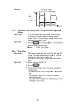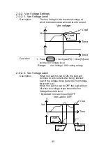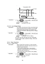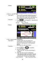
38
Operation
1.
Make sure the load is off.
2.
Press
Main
.
3.
Select Dynamic or Static mode with the
Function[F4]
soft-key.
A different switching mode can be set for CC,
CR and CP mode.
4.
For dynamic mode, set the Timer1 and Timer2
parameters using the scroll wheel and number
pad.
Timer1 sets the Level1 on-time.
Timer2 sets the Level2 on-time.
Take the slew rate settings into consideration
when setting the timers.
The frequency of the dynamic switching is
output via the TRIG OUT BNC.
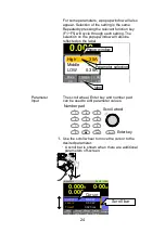
To select whether A Value or B Value is the
“active” setting, press the
Shift
+
Preset
keys.
The “active” value will be shown in the
Operation Status Panel.
The load can be “on” when switching between
A Value and B Value.
Display:
Static Mode
Mode
CP
I Range
H 35A
V Range
H 150V
Function
Static
Configure
0.00
V
0.000
A
0.00
w
CP B Value
0.00
CP A Value
0.00
LOAD
RS232
A Value
Fine
31/Oct/2013
W
W
Active setting
A Value
B Value
+CV
OFF V
Static mode
Summary of Contents for LSG SERIES
Page 8: ......
Page 23: ...11 GRA 414 E EIA standard 132 382 5 477 6 GRA 414 J JIS standard 149 382 5 477 6 ...
Page 149: ...137 7 6 Operating Area LSG 175 ...
Page 150: ...138 LSG 350 ...
Page 151: ...139 LSG 1050 ...
Page 166: ......

