30
6.
Set the resistance or conductance level
parameters using the scroll wheel and number
pad.
For Static mode, set
CR A Value
and/or
CR B
Value
.
For Dynamic mode, set
Level1
and
Level2
.
The maximum and minimum conductance/
resistance levels depend on the selected
current range.
7.
To add CV mode to CR mode (CR+CV), see
page 33.
8.
Set the remaining basic configuration settings
such as the slew rate, and switching mode
settings. See page 37 for details.
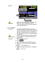
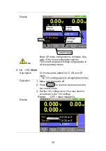
Display
Mode
CR
I Range
H 35A
V Range
L 15V
Function
Static
Configure
0.000
V
0.000
A
0.00
w
SlewRate
250.000
CR B Value
0.04082
CR A Value
0.04082
LOAD
RS232
A Value
Fine
31/Oct/2013
mA/uS
Ω
Ω
Mode
Current range
Voltage
range
Active
setting
Conductance/
Resistances
Conductance/
Resistance
settings
Note
Basic CR mode configuration is complete. See
page 37 for more configuration options.
The current range and voltage range applies to
all the operating modes.
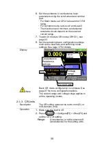
2-1-3. CR Units
Description
The CR setting units can be set to ohm (Ω) or
milli-siemens (mS).
Operation
1.
Make sure the load is off.
2.
Press
Main
>
Configure[F5]
>
Other[F2]
and
set the
CR Unit
setting.
Range:
Ω (resistance) or milli-siemens,mS
(conductance) for the setting units.
Summary of Contents for LSG SERIES
Page 8: ......
Page 23: ...11 GRA 414 E EIA standard 132 382 5 477 6 GRA 414 J JIS standard 149 382 5 477 6 ...
Page 149: ...137 7 6 Operating Area LSG 175 ...
Page 150: ...138 LSG 350 ...
Page 151: ...139 LSG 1050 ...
Page 166: ......

