MAX 10 Plus User
Manual
46
May 31, 2019
◼
Demonstration Setup
•
Please make sure Quartus II and USB-Blaster II driver are installed on the host PC.
•
Connect the USB cable from the USB-Blaster II port (J8) on the MAX 10 Plus board to the host
PC and power on the MAX 10 Plus board.
•
Execute
the
demo
batch
file
“ps2_mouse.bat”
under
the
folder
Demonstrations\ps2_mouse\demo_batch\.
•
Plug in the PS/2 mouse.
•
Press KEY0 to enable data transfer.
•
Press KEY1 to clear the display data cache.
•
The 7-segment display shows X displacement when SW0 is low, and Y displacement when SW0
is high. The display should change when the PS/2 mouse moves.
•
The LEDR [2:0] will blink according to
when the left-button, right-button, and/or
middle-button is pressed.
Table 5-1
Description of 7-segment Display and LED Indicators
Indicator Name Description
LEDR0
Left button press indicator
LEDR1
Right button press indicator
LEDR2
Middle button press indicator
HEX0
Low byte of X/Y displacement
HEX1
High byte of X/Y displacement
5.2
ADC Potentiometer
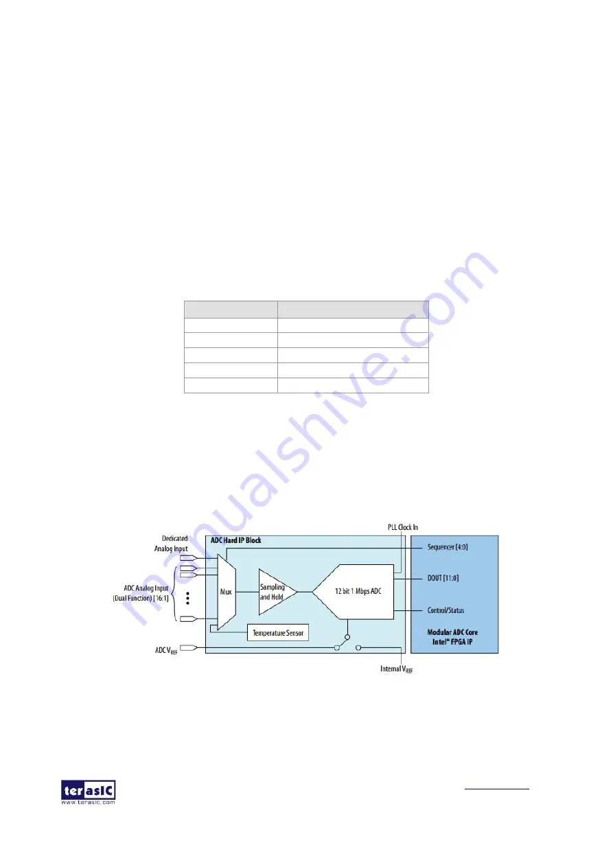
Nowadays voltage and current monitors play a significant role in high-reliability system. Most of
applications can be implemented by an Analog-to-Digital Converter (ADC). MAX 10 Plus board
provides a potentiometer demonstration using the ADC in MAX10. This ADC solution consists of
hard IP blocks in MAX 10 device and soft logic through Intel Modular ADC IP core.
shows the block diagram of ADC hard IP block in MAX10 device.
Figure 5-2 Block Diagram of ADC Hard IP Block
This demo uses 2nd ADC of MAX10 on channel 8. The ADC settings are shown in


