MAINTENANCE
550E MM149 (6--97)
3-26
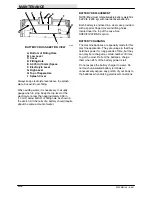
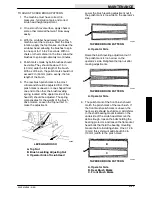
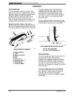
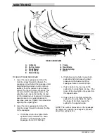
2. SQUEEGEE LIFT CYLINDER
The squeegee lift cylinder rod end should be
adjusted so there is 5.50
+
0.12 in
(140
+
3 mm) between the cylinder rod hole
and the rod end hole for machines below
serial number 004506. For machines serial
number 004507 and above, the adjustment
should be 6.00
+
0.12 in (150
+
3 mm).
B
A
01725
SQUEEGEE LIFT CYLINDER
A. Cylinder
B. Adjustment Length
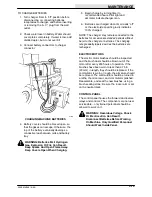
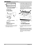
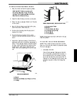
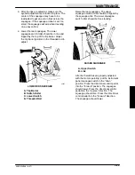
3. EYEBOLTS
The eyebolts should be adjusted so there is
1.38
+
0.12 in (35
+
3 mm) between the end
of the eyebolt and the top of the arm on
each side of squeegee.
C
A
B
01726
EYEBOLT
A. Eyebolt
B. 1.38
+
0.12 in (35
+
3 mm)
C. Arm
4. CASTERS
The casters should be in good condition and
be free to spin. The center caster should be
0.25
+
0.06 in (6
+
2 mm) off the floor with
the squeegee blade perpendicular to the
floor. The tip casters should touch the floor
with the squeegee blade perpendicular to
the floor.
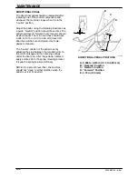
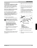
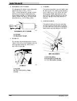
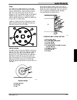
5. ARM CLEARANCE
The distance between the arm assembly
and the squeegee lift shaft arm should be 1
to 1.25 in (25 to 30 mm) with the squeegee
blade down and perpendicular to the floor.
B
A
C
01728
ARM CLEARANCE
A. Arm Assembly
B. Squeegee Lift Shaft Arm
C. 1 to 1.25 in (25 to 30 mm)
Summary of Contents for 550
Page 10: ...GENERAL INFORMATION 550E MM149 3 94 viii ...
Page 12: ...OPERATION 550E MM149 3 91 2 2 ...
Page 30: ...OPERATION 550E MM149 9 00 2 20 ...
Page 32: ...MAINTENANCE 550E MM149 3 91 3 2 ...
Page 62: ...MAINTENANCE 550E MM149 2 05 3 32 ...
Page 66: ...APPENDIX 550E MM149 3 91 4 4 ...
Page 74: ...STANDARD PARTS 550E MM149 5 01 6 4 Fig 2 Replacement Brushes 1 ...
Page 96: ...STANDARD PARTS 550E MM149 5 01 6 26 Fig 17 Electric Motor Group 1 2 3 4 5 6 ...
Page 105: ...STANDARD PARTS 6 35 550E MM149 5 01 Fig 23 Electrical Schematic 1 2 3 4 5 01228 550E ...
Page 106: ...STANDARD PARTS 550E MM149 5 01 6 36 Fig 23 Electrical Schematic 1 2 3 4 5 01228 550E ...
Page 117: ...STANDARD PARTS 6 47 550E MM149 5 01 Fig 31 Hydraulic Schematic 001330 005607 02361 550E ...
Page 118: ...STANDARD PARTS 550E MM149 5 01 6 48 Fig 32 Hydraulic Schematic 005608 11118 550E ...
Page 168: ...OPTIONS 550E MM149 9 99 8 18 ...
Page 182: ...BREAKDOWNS 550E MM149 10 10 9 14 ...

