MAINTENANCE
3-29
550E MM149 (6--97)
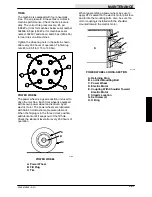
3. After the tips are adjusted, make sure the
eyebolt adjustments are locked in place. The
center of the squeegee may have to be
readjusted to get an even rollout across the
squeegee. If the squeegee rollout is set too
small, the squeegee will skip when traveling
on a uneven floor.
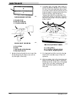
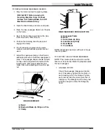
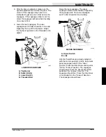
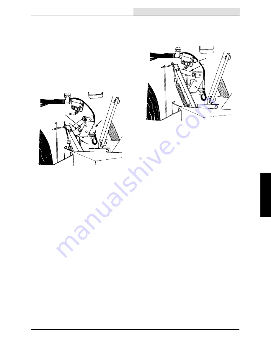
4. Lower the rear squeegee. The lower
squeegee switch roller should be in line and
tripped by the top of the trip barrel. Adjust
the trip barrel position on the threaded rod to
adjust.
C
B
A
D
02357
LOWERED SQUEEGEE
A. Trip Barrel
B. Switch Roller
C. Lower Switch
D. Threaded Rod
Raise the rear squeegee. The upper
squeegee switch roller should be tripped by
the squeegee link. The lower squeegee
switch roller should be free standing.
A
B
02358
RAISED SQUEEGEE
A. Upper Switch
B. Link
After both switches are properly adjusted
with the motor operating, put the instrument
panel squeegee switch in the “down”
position. Press the directional control pedal
into the “forward” position. The squeegee
should lower. Press the directional control
pedal into the “reverse” direction. The
squeegee should rise. Press the directional
control pedal into the “forward” direction.
The squeegee should lower.
Summary of Contents for 550
Page 10: ...GENERAL INFORMATION 550E MM149 3 94 viii ...
Page 12: ...OPERATION 550E MM149 3 91 2 2 ...
Page 30: ...OPERATION 550E MM149 9 00 2 20 ...
Page 32: ...MAINTENANCE 550E MM149 3 91 3 2 ...
Page 62: ...MAINTENANCE 550E MM149 2 05 3 32 ...
Page 66: ...APPENDIX 550E MM149 3 91 4 4 ...
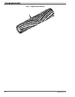
Page 74: ...STANDARD PARTS 550E MM149 5 01 6 4 Fig 2 Replacement Brushes 1 ...
Page 96: ...STANDARD PARTS 550E MM149 5 01 6 26 Fig 17 Electric Motor Group 1 2 3 4 5 6 ...
Page 105: ...STANDARD PARTS 6 35 550E MM149 5 01 Fig 23 Electrical Schematic 1 2 3 4 5 01228 550E ...
Page 106: ...STANDARD PARTS 550E MM149 5 01 6 36 Fig 23 Electrical Schematic 1 2 3 4 5 01228 550E ...
Page 117: ...STANDARD PARTS 6 47 550E MM149 5 01 Fig 31 Hydraulic Schematic 001330 005607 02361 550E ...
Page 118: ...STANDARD PARTS 550E MM149 5 01 6 48 Fig 32 Hydraulic Schematic 005608 11118 550E ...
Page 168: ...OPTIONS 550E MM149 9 99 8 18 ...
Page 182: ...BREAKDOWNS 550E MM149 10 10 9 14 ...

