MAINTENANCE
3-23
550E MM149 (12--05)
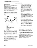
SOLUTION DISPENSING TUBE
The solution dispensing tube has a flushing
connection built in. The flushing connection is the
tee fitting next to the solution control valve. This
allows a garden hose to be threaded into the
dispensing system to flush the system. Flush the
system after every 50 hours of operation.
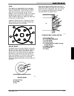
SRS CLEANING SOLUTION FILTER
The cleaning solution filter has been provided to
filter cleaning solution before it enters the main
supply hoses or pump. It is mounted on the top
front right side of the solution tank. Clean the filter
after every 50 hours of operation on machines
before serial number 001439.
SRS METERING SOLUTION PUMP
A bellows pump meters cleaning solution into the
recycling solution at rates of one-quarter, one-half
and one percent. The cleaning solution is
introduced to the recycling solution at a point just
before the spray nozzle. Clean the metering pump
daily when cleaning the solution tank.
TROUBLESHOOTING
Low Flow
1. Poppet valves dirty, dried cleaning solution
residue on valves.
2. Restriction in cleaning solution lines.
3. Air leak at pump intake.
4. Defective wiring or motor.
Motor Fails to Turn On
1. Loose wiring connection.
2. Defective motor.
Motor Operates, But No Pump Discharge
1. Damaged bellows.
2. Restriction in cleaning solution lines.
3. Air leak in intake line.
4. Unprimed pump.
a. Remove pump inlet hose.
b. Fill pump chamber with approximately
one ounce SRS solution.
c. Reinstall pump inlet hose.
d. Pump should start metering tank
solution after 3 to 4 minutes run time.
Summary of Contents for 550
Page 10: ...GENERAL INFORMATION 550E MM149 3 94 viii ...
Page 12: ...OPERATION 550E MM149 3 91 2 2 ...
Page 30: ...OPERATION 550E MM149 9 00 2 20 ...
Page 32: ...MAINTENANCE 550E MM149 3 91 3 2 ...
Page 62: ...MAINTENANCE 550E MM149 2 05 3 32 ...
Page 66: ...APPENDIX 550E MM149 3 91 4 4 ...
Page 74: ...STANDARD PARTS 550E MM149 5 01 6 4 Fig 2 Replacement Brushes 1 ...
Page 96: ...STANDARD PARTS 550E MM149 5 01 6 26 Fig 17 Electric Motor Group 1 2 3 4 5 6 ...
Page 105: ...STANDARD PARTS 6 35 550E MM149 5 01 Fig 23 Electrical Schematic 1 2 3 4 5 01228 550E ...
Page 106: ...STANDARD PARTS 550E MM149 5 01 6 36 Fig 23 Electrical Schematic 1 2 3 4 5 01228 550E ...
Page 117: ...STANDARD PARTS 6 47 550E MM149 5 01 Fig 31 Hydraulic Schematic 001330 005607 02361 550E ...
Page 118: ...STANDARD PARTS 550E MM149 5 01 6 48 Fig 32 Hydraulic Schematic 005608 11118 550E ...
Page 168: ...OPTIONS 550E MM149 9 99 8 18 ...
Page 182: ...BREAKDOWNS 550E MM149 10 10 9 14 ...

