MAINTENANCE
550E MM149 (6--97)
3-18
B
C
A
00082
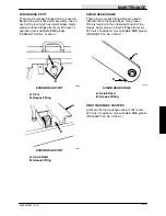
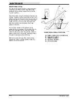
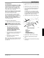
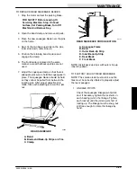
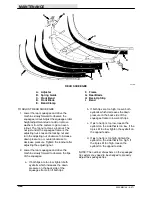
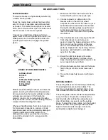
TAPERED BRUSH PATTERN
A. Operator Side
B. Rear Brush Marks
C. Front Brush Marks
A
D
C
B
00284
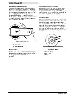
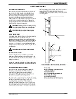
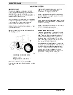
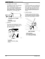
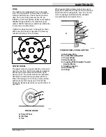
BRUSH SHAFT MOUNTING
A. Scrub Head
B. Shim
C. Bearing Mounting Bracket
D. Bearing Protector
7. Recheck the brush polish marks to see if the
front and rear match, and are even across
the full length of the brush.
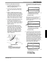
8. The width of the rear brush polish mark can
vary more than the desired 1.5 to 2 in (40 to
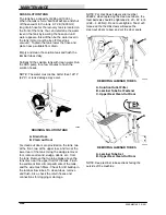
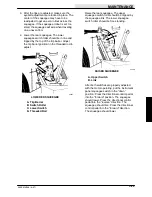
50 mm). There are adjusting knobs located
on the drive side of the scrub head. Turn the
knob clockwise to decrease the width of the
polish mark and counterclockwise to
increase the width of the polish mark. The
polish mark should not exceed 2 in (50 mm).
Use the locking strips to keep the adjusting
knobs in place.
A
B
C
00286
BRUSH ADJUSTMENT KNOBS
A. Locking Strips
B. Front Brush Adjusting Knob
C. Rear Brush Adjusting Knob
9. For maximum brush life, rotate the brushes
from front-to-rear after every 50 hours of
operation.
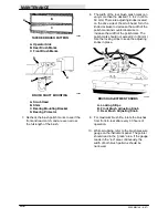
10. While scrubbing, refer to the brush pressure
gauge on the instrument panel. The pointer
should read in the “green” area. If the gauge
reads in the “red” area continuously, the
width of both brush patterns should be
narrowed.
Summary of Contents for 550
Page 10: ...GENERAL INFORMATION 550E MM149 3 94 viii ...
Page 12: ...OPERATION 550E MM149 3 91 2 2 ...
Page 30: ...OPERATION 550E MM149 9 00 2 20 ...
Page 32: ...MAINTENANCE 550E MM149 3 91 3 2 ...
Page 62: ...MAINTENANCE 550E MM149 2 05 3 32 ...
Page 66: ...APPENDIX 550E MM149 3 91 4 4 ...
Page 74: ...STANDARD PARTS 550E MM149 5 01 6 4 Fig 2 Replacement Brushes 1 ...
Page 96: ...STANDARD PARTS 550E MM149 5 01 6 26 Fig 17 Electric Motor Group 1 2 3 4 5 6 ...
Page 105: ...STANDARD PARTS 6 35 550E MM149 5 01 Fig 23 Electrical Schematic 1 2 3 4 5 01228 550E ...
Page 106: ...STANDARD PARTS 550E MM149 5 01 6 36 Fig 23 Electrical Schematic 1 2 3 4 5 01228 550E ...
Page 117: ...STANDARD PARTS 6 47 550E MM149 5 01 Fig 31 Hydraulic Schematic 001330 005607 02361 550E ...
Page 118: ...STANDARD PARTS 550E MM149 5 01 6 48 Fig 32 Hydraulic Schematic 005608 11118 550E ...
Page 168: ...OPTIONS 550E MM149 9 99 8 18 ...
Page 182: ...BREAKDOWNS 550E MM149 10 10 9 14 ...

