MAINTENANCE
550E MM149 (6--96)
3-24
SQUEEGEES
SIDE SQUEEGEES
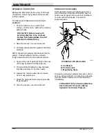
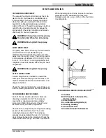
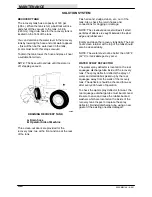
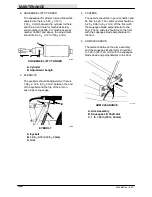
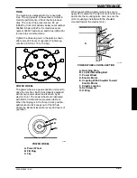
The side squeegees control scrub brush water
spray. They consist of a squeegee blade, backup
strip, band, and clamp. Check the side squeegee
blades for damage or wear daily. Replace
squeegee blade by opening the quick-release
latch and removing the band. Remove the
bracket, old blade, and backup strip. Replace the
squeegee blade and backup strip, if it is worn.
Adjust the squeegee clamp so that there is
adequate pressure to hold the squeegee blade in
place. The squeegee blade should be held so that
it cannot be pulled from between the locating pins.
D
A
C
I H
E
F
G
B
00302
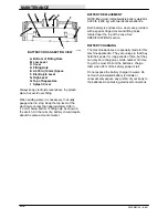
SIDE SQUEEGEE ASSEMBLY
A. Retaining Band
B. Latch
C. Door Locking Pin
D. Door
E. Flap
F. Door Latch
G. Squeegee Frame
H. Backup Strip
I. Squeegee Blade
The side squeegee frame is attached to the
squeegee door with four screws. The screw
mounting holes are slotted, allowing vertical
adjustment of the squeegee blade by simply
loosening the screws and moving the squeegee
up or down. Check the side squeegee blades
adjustment daily.
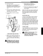
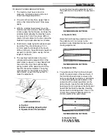
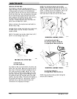
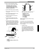
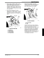
Lower the head and adjust the squeegee so that
the blade deflects 0.50 in (13 mm). The squeegee
should deflect evenly across its entire length.
A
B
00289
SIDE SQUEEGEE BLADE DEFLECTION
A. Side Squeegee Blade
B. 0.50 in (13 mm) Deflection
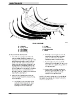
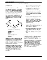
REAR SQUEEGEE
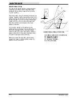
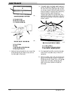
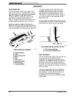
The rear squeegee assembly channels water into
the vacuum fan suction. When properly
maintained, the squeegee should leave floors
nearly dry. The assembly consists of a front and
rear blade held in place by bands and clamps.
Two back-up strips are used with the rear blade.
Check the rear squeegee for damage or wear and
adjustment daily.
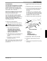
The rear squeegee has been factory adjusted.
The factory adjustments need to be done only
after replacing a major component of the rear
squeegee assembly. Regular squeegee
adjustments are covered in
TO ADJUST REAR
SQUEEGEE
.
Summary of Contents for 550
Page 10: ...GENERAL INFORMATION 550E MM149 3 94 viii ...
Page 12: ...OPERATION 550E MM149 3 91 2 2 ...
Page 30: ...OPERATION 550E MM149 9 00 2 20 ...
Page 32: ...MAINTENANCE 550E MM149 3 91 3 2 ...
Page 62: ...MAINTENANCE 550E MM149 2 05 3 32 ...
Page 66: ...APPENDIX 550E MM149 3 91 4 4 ...
Page 74: ...STANDARD PARTS 550E MM149 5 01 6 4 Fig 2 Replacement Brushes 1 ...
Page 96: ...STANDARD PARTS 550E MM149 5 01 6 26 Fig 17 Electric Motor Group 1 2 3 4 5 6 ...
Page 105: ...STANDARD PARTS 6 35 550E MM149 5 01 Fig 23 Electrical Schematic 1 2 3 4 5 01228 550E ...
Page 106: ...STANDARD PARTS 550E MM149 5 01 6 36 Fig 23 Electrical Schematic 1 2 3 4 5 01228 550E ...
Page 117: ...STANDARD PARTS 6 47 550E MM149 5 01 Fig 31 Hydraulic Schematic 001330 005607 02361 550E ...
Page 118: ...STANDARD PARTS 550E MM149 5 01 6 48 Fig 32 Hydraulic Schematic 005608 11118 550E ...
Page 168: ...OPTIONS 550E MM149 9 99 8 18 ...
Page 182: ...BREAKDOWNS 550E MM149 10 10 9 14 ...

