MAINTENANCE
3-31
550E MM149 (5--01)
TIRES
The machine is equipped with four pneumatic
tires. The air pressure in these tires is critical to
machine performance. Check the tire pressure
daily. The correct tire pressures are: 85 psi
(585 kPa) front for machines below serial number
004506; 65 psi (450 kPa) for machines serial
number 004507 and above; and 35 psi (240 kPa)
for rear tires on all machines.
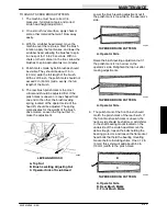
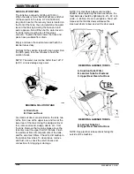
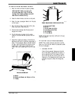
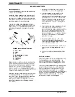
Tighten the wheel lug nuts in the pattern shown,
after every 200 hours of operation. Tighten lug
nuts 85 to 95 ft lb (115 to 130 Nm).
2
3
4
1
5
6
POWER WHEEL
The power wheel is a gear reduction unit used to
drive the machine. Each front wheel is equipped
with its own power wheel and is driven by an
electric motor. The power wheels are lubricated
with SAE 90 mild-extreme pressure lubricant.
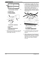
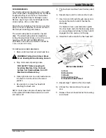
When the fill plug is in the three o’clock position,
add lubricant until it seeps out of the fill hole.
Check the lubricant level after every 200 hours of
operation.
A
B
C
01149
POWER WHEEL
A. Power Wheel
B. Fill Plug
C. Tire
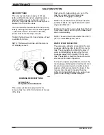
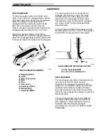
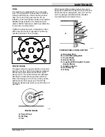
When reassembling a power wheel, be sure to
apply RTV sealant on the electric motor pilot face
and loctite the mounting bolts. Also, be sure the
motor coupling is installed with the shoulder
mounted toward the electric motor.
A
B
C
D
E
F
G
H
01149
POWER WHEEL CROSS-SECTION
A. Retaining Ring
B. Loctited Mounting Bolt
C. Power Wheel
D. Electric Motor
E. Coupling With Shoulder Toward
Electric Motor
F. Silastic Location
G. Set Screw (2)
H. O-Ring
Summary of Contents for 550
Page 10: ...GENERAL INFORMATION 550E MM149 3 94 viii ...
Page 12: ...OPERATION 550E MM149 3 91 2 2 ...
Page 30: ...OPERATION 550E MM149 9 00 2 20 ...
Page 32: ...MAINTENANCE 550E MM149 3 91 3 2 ...
Page 62: ...MAINTENANCE 550E MM149 2 05 3 32 ...
Page 66: ...APPENDIX 550E MM149 3 91 4 4 ...
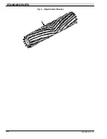
Page 74: ...STANDARD PARTS 550E MM149 5 01 6 4 Fig 2 Replacement Brushes 1 ...
Page 96: ...STANDARD PARTS 550E MM149 5 01 6 26 Fig 17 Electric Motor Group 1 2 3 4 5 6 ...
Page 105: ...STANDARD PARTS 6 35 550E MM149 5 01 Fig 23 Electrical Schematic 1 2 3 4 5 01228 550E ...
Page 106: ...STANDARD PARTS 550E MM149 5 01 6 36 Fig 23 Electrical Schematic 1 2 3 4 5 01228 550E ...
Page 117: ...STANDARD PARTS 6 47 550E MM149 5 01 Fig 31 Hydraulic Schematic 001330 005607 02361 550E ...
Page 118: ...STANDARD PARTS 550E MM149 5 01 6 48 Fig 32 Hydraulic Schematic 005608 11118 550E ...
Page 168: ...OPTIONS 550E MM149 9 99 8 18 ...
Page 182: ...BREAKDOWNS 550E MM149 10 10 9 14 ...

