MAINTENANCE
550E MM149 (6--96)
3-20
SOLUTION SYSTEM
RECOVERY TANK
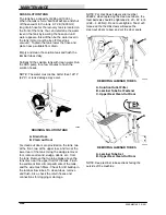
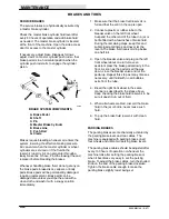
The recovery tank has a capacity of 120 gal
(455 L). When the tank is full, a ball float will rise
and shut off the vacuum to the tank. A 48 in
(220 mm) long drain hose for the recovery tank is
located on the front of the tank.
You can determine the water level in the recovery
tank by lowering the hose end until water appears
-- this will then be the water level in the tank,
(motor must be off; this stops vacuum).
To drain the tank, lower the hose and place it near
a suitable floor drain.
NOTE: The hose will not drain until the motor is
off, stopping vacuum.
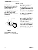
00288
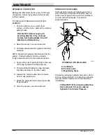
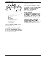
DRAINING RECOVERY TANK
A. Drain hose
B. Operator Side of Machine
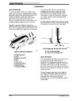
Three clean-out doors are provided for the
recovery tank: two at the front and one at the rear
of the tank.
Flush all sand, sludge, debris, etc., out of the
tank. Also, check the return hoses and
connections for clogging or damage.
NOTE: The cleanout door seal will leak if small
particles of debris are caught between the door
edge and rubber seal.
Empty and clean the recovery tank daily. The ball
float screen retainer at the top of the tank should
also be cleaned daily.
NOTE: The water must not be hotter than 130
_
F
(54
_
C) or tank damage may occur.
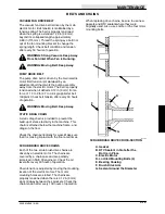
WATER SPRAY DEFLECTOR
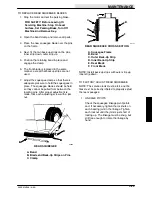
The water spray deflector is located on the rear
squeegee discharge tube inside of the recovery
tank. The spray deflector deflects the spray of
water and small debris picked up by the rear
squeegee away from the walls of the recovery
tank. The deflector should be checked for wear
after every 200 hours of operation.
To check the water spray deflector for wear, the
rear squeegee discharge tube must be removed.
Be sure to save and reuse the rubber-backed
washers which are located on the inside of the
recovery tank. Inspect or replace the spray
deflector. Reinstall discharge tube, using a new
gasket if the existing one was damaged.
Summary of Contents for 550
Page 10: ...GENERAL INFORMATION 550E MM149 3 94 viii ...
Page 12: ...OPERATION 550E MM149 3 91 2 2 ...
Page 30: ...OPERATION 550E MM149 9 00 2 20 ...
Page 32: ...MAINTENANCE 550E MM149 3 91 3 2 ...
Page 62: ...MAINTENANCE 550E MM149 2 05 3 32 ...
Page 66: ...APPENDIX 550E MM149 3 91 4 4 ...
Page 74: ...STANDARD PARTS 550E MM149 5 01 6 4 Fig 2 Replacement Brushes 1 ...
Page 96: ...STANDARD PARTS 550E MM149 5 01 6 26 Fig 17 Electric Motor Group 1 2 3 4 5 6 ...
Page 105: ...STANDARD PARTS 6 35 550E MM149 5 01 Fig 23 Electrical Schematic 1 2 3 4 5 01228 550E ...
Page 106: ...STANDARD PARTS 550E MM149 5 01 6 36 Fig 23 Electrical Schematic 1 2 3 4 5 01228 550E ...
Page 117: ...STANDARD PARTS 6 47 550E MM149 5 01 Fig 31 Hydraulic Schematic 001330 005607 02361 550E ...
Page 118: ...STANDARD PARTS 550E MM149 5 01 6 48 Fig 32 Hydraulic Schematic 005608 11118 550E ...
Page 168: ...OPTIONS 550E MM149 9 99 8 18 ...
Page 182: ...BREAKDOWNS 550E MM149 10 10 9 14 ...


