OPERATION
550E MM149 (9--00)
2-18
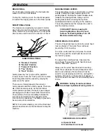
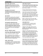
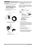
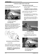
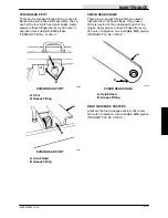
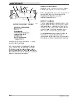
10.Tie the rear of the machine under the rear
bumper at the two bumper mounts.
A
REAR TIE DOWN LOCATION
A. Rear Bumper Mounts
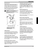
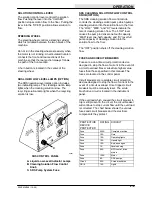
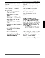
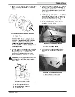
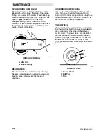
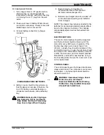
11. If the machine is equipped with the optional
scrub head support legs, pull the pins to
lower the legs. Lock them into position again
by replacing the pins.
A
B
C
OPTIONAL SCRUB HEAD SUPPORT LEG
A. Scrub Head
B. Support Leg
C. Pin
12.If the loading surface is not horizontal or is
higher than 380 mm (15 in) from the ground,
use a winch to unload machine.
If the loading surface is horizontal AND is
380 mm (15 in) or less from the ground, the
machine may be driven off the truck or
trailer.
FOR SAFETY: When unloading machine
off truck or trailer, use winch. Do not
drive the machine off the truck or trailer
unless the loading surface is horizontal
AND 380 mm (15 in) or less from the
ground.
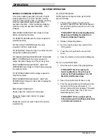
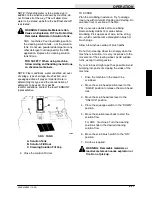
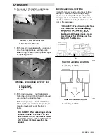
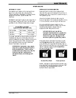
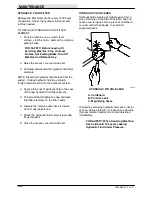
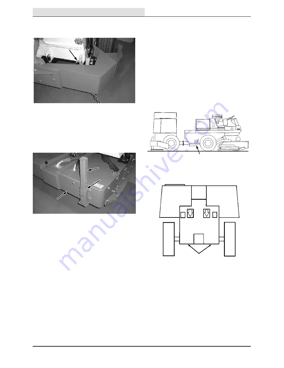
MACHINE JACKING LOCATIONS
Empty the recovery and solution tanks before
jacking the machine. The machine jacking
locations are labeled with a label. The tractor
jacking locations are behind each of the front
wheels, and the tank jacking locations are in the
front of the rear wheels.
FOR SAFETY: When Servicing Machine,
Block Machine Tires Before Jacking
Machine Up. Jack Machine Up At
Designated Locations Only. Block
Machine Up With Jack Stands. Use A
Hoist Or Jack That Will Support The
Weight Of The Machine.
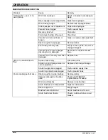
A
00438
TRACTOR JACKING LOCATION
A. Jacking Location
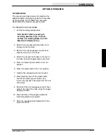
A
01820
TANK JACKING LOCATION
A. Jacking Location
Summary of Contents for 550
Page 10: ...GENERAL INFORMATION 550E MM149 3 94 viii ...
Page 12: ...OPERATION 550E MM149 3 91 2 2 ...
Page 30: ...OPERATION 550E MM149 9 00 2 20 ...
Page 32: ...MAINTENANCE 550E MM149 3 91 3 2 ...
Page 62: ...MAINTENANCE 550E MM149 2 05 3 32 ...
Page 66: ...APPENDIX 550E MM149 3 91 4 4 ...
Page 74: ...STANDARD PARTS 550E MM149 5 01 6 4 Fig 2 Replacement Brushes 1 ...
Page 96: ...STANDARD PARTS 550E MM149 5 01 6 26 Fig 17 Electric Motor Group 1 2 3 4 5 6 ...
Page 105: ...STANDARD PARTS 6 35 550E MM149 5 01 Fig 23 Electrical Schematic 1 2 3 4 5 01228 550E ...
Page 106: ...STANDARD PARTS 550E MM149 5 01 6 36 Fig 23 Electrical Schematic 1 2 3 4 5 01228 550E ...
Page 117: ...STANDARD PARTS 6 47 550E MM149 5 01 Fig 31 Hydraulic Schematic 001330 005607 02361 550E ...
Page 118: ...STANDARD PARTS 550E MM149 5 01 6 48 Fig 32 Hydraulic Schematic 005608 11118 550E ...
Page 168: ...OPTIONS 550E MM149 9 99 8 18 ...
Page 182: ...BREAKDOWNS 550E MM149 10 10 9 14 ...

