OPERATION
2-9
550E MM149 (12--05)
SOLUTION CONTROL LEVER
The solution control lever controls the solution
flow. Pushing the lever into the “CLOSED”
position stops solution flow to the floor. Pulling the
lever into the “OPEN” position allows solution to
flow.
STEERING WHEEL
The steering wheel controls a steering cylinder
which is mounted between the two halves of the
machine.
Do not turn the steering wheel excessively when
the motor is not running. An articulated trunnion
connects the front and rear sections of the
machine so that the rear section always follows
the path of the front section.
A horn button is located in the center of the
steering wheel.
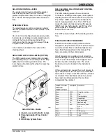
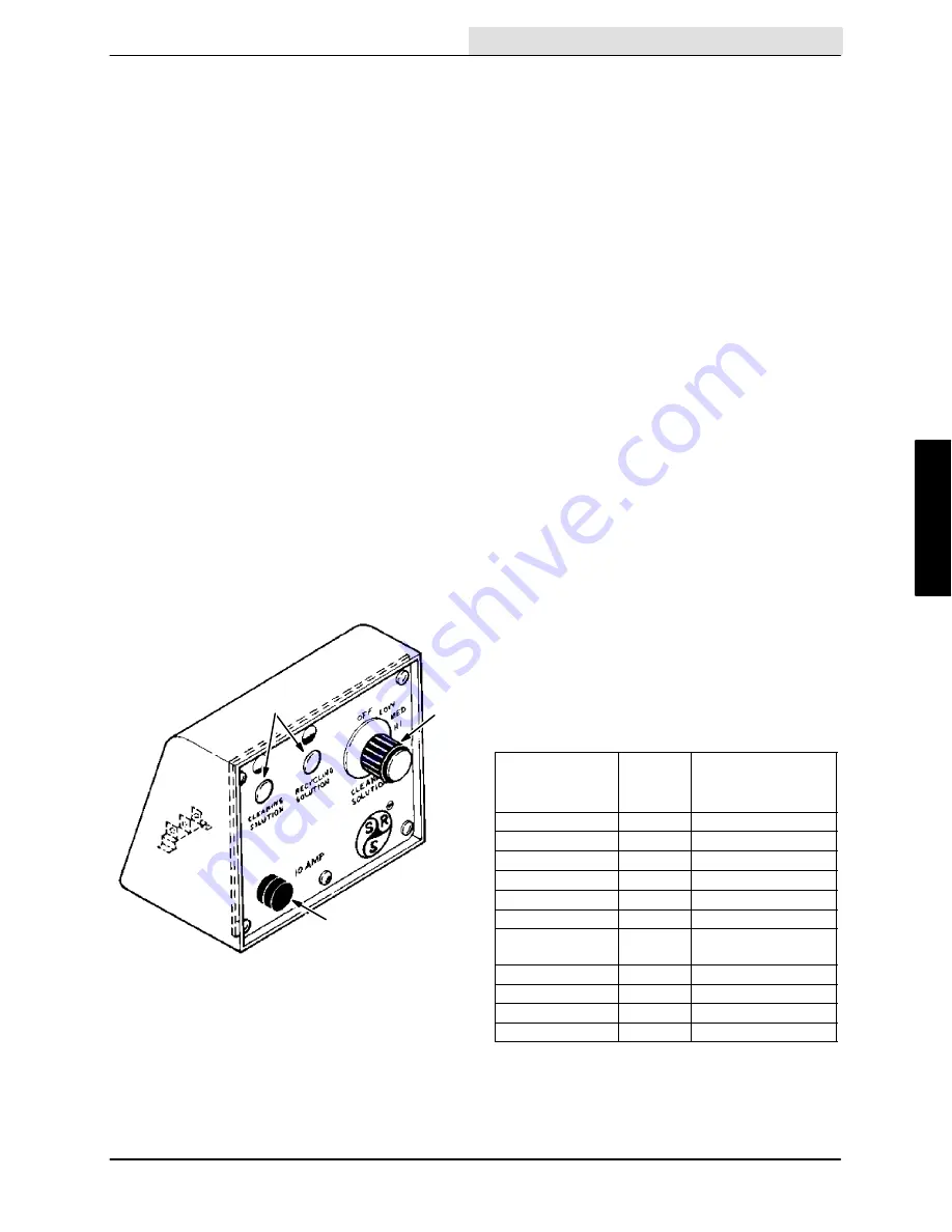
SRS LIQUID LOW LEVEL LAMPS (OPTION)
The SRS liquid low level lamps option includes
two indicating lamps. The cleaning solution lamp
lights when the cleaning solution is low. The
recycling solution lamp lights when the recycling
solution is low.
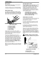
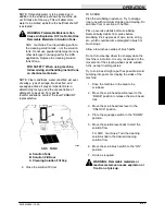
A
B
C
00351
SRS CONTROL PANEL
A. Liquid Low Level Indicator Lamps
B. Cleaning Solution Flow Control
Knob
C. SRS Pump System Fuse
SRS CLEANING SOLUTION FLOW CONTROL
KNOB (OPTION)
The SRS cleaning solution flow control knob
controls the cleaning solution pump which pumps
cleaning solution into the solution flow to the floor.
The “LOW,” “MED,” and “HI” levels indicate the
rate of cleaning solution flow. The “LOW” level
causes the pump to deliver one-fourth capacity,
“MED” level one-half capacity, and “HI” level full
pump capacity of cleaning solution into the
solution flow to the floor.
The “OFF” position shuts off the cleaning solution
flow.
FUSES AND CIRCUIT BREAKERS
Fuses are a one-time circuit protection device
designed to stop the flow of current in the event of
a circuit overload. Never substitute higher value
fuses than those specified in this manual. The
fuses are located in the control panel.
Circuit breakers are resetable circuit protection
devices designed to stop the flow of current in the
event of a circuit overload. Once tripped, circuit
breakers must be manually reset. The scrub
brush drive circuit is located in the instrument
panel.
If the overload which caused the circuit breaker to
trip is still present in the circuit, the circuit breaker
will continue to stop current flow until the overload
is corrected. The chart below shows the various
fuses and circuit breakers and the electrical
components they protect.
PROTECTIVE
DEVICE
PROTECTED
RATING CIRCUIT
Fuse
200 A
Complete machine
Fuse
15 A
Horn
Fuse
15 A
Operating lights
Fuse
15 A
Hazard light
Fuse
15 A
Auto--squeegee
Fuse
1 A
Level sensing
Fuse
50 A
MFR control, drive
Fuse
50 A
MFR control, drive
motors
Fuse
120 A
Motor
Fuse
5 A
SRS pumps
Circuit
30 A
Scrub brush drive
CB--6
15 A
Lights
Summary of Contents for 550
Page 10: ...GENERAL INFORMATION 550E MM149 3 94 viii ...
Page 12: ...OPERATION 550E MM149 3 91 2 2 ...
Page 30: ...OPERATION 550E MM149 9 00 2 20 ...
Page 32: ...MAINTENANCE 550E MM149 3 91 3 2 ...
Page 62: ...MAINTENANCE 550E MM149 2 05 3 32 ...
Page 66: ...APPENDIX 550E MM149 3 91 4 4 ...
Page 74: ...STANDARD PARTS 550E MM149 5 01 6 4 Fig 2 Replacement Brushes 1 ...
Page 96: ...STANDARD PARTS 550E MM149 5 01 6 26 Fig 17 Electric Motor Group 1 2 3 4 5 6 ...
Page 105: ...STANDARD PARTS 6 35 550E MM149 5 01 Fig 23 Electrical Schematic 1 2 3 4 5 01228 550E ...
Page 106: ...STANDARD PARTS 550E MM149 5 01 6 36 Fig 23 Electrical Schematic 1 2 3 4 5 01228 550E ...
Page 117: ...STANDARD PARTS 6 47 550E MM149 5 01 Fig 31 Hydraulic Schematic 001330 005607 02361 550E ...
Page 118: ...STANDARD PARTS 550E MM149 5 01 6 48 Fig 32 Hydraulic Schematic 005608 11118 550E ...
Page 168: ...OPTIONS 550E MM149 9 99 8 18 ...
Page 182: ...BREAKDOWNS 550E MM149 10 10 9 14 ...

