OPERATION
2-7
550E MM149 (8--02)
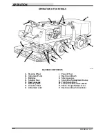
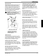
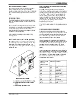
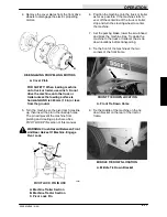
PIVOT LOCK PIN
A pivot lock pin is provided to lock the pivot joint
located between the front and rear machine
sections. The pin is hung on the front section of
the machine adjacent to the machine pivot. To
lock the sections, turn the machine so the pivot
lock holes line up, then insert the pin through the
holes. The pin will prevent the machine from
pivoting and creating a pinch area.
WARNING: Crush Hazard Between Front
And Rear Halves Of Machine. Put
Locking Pin In Pivot Lock Before Going
Between Machine Halves.
B
C
A
00251
PIVOT LOCK PIN IN USE
A. Machine Trailer Section
B. Machine Tractor Section
C. Pivot Lock Pin
OPERATOR SEAT
The operator seat is of a fixed back style with a
forward-backward adjustment. To adjust the seat,
loosen the seat mounting bolts, slide the seat to
the position desired, and tighten the bolts.
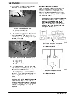
HAZARD LIGHT SWITCH (OPTION)
The hazard light switch is present on machines
with the hazard light option. Flip the switch toggle
up to turn the light on. Flip the switch toggle down
to turn the light off.
ROTATING LIGHT SWITCH (OPTION)
The rotating light switch is present on machines
with the rotating light switch option. Flip the switch
toggle up to turn the light on. Flip the switch
toggle down to turn light off.
OPERATING LIGHTS SWITCH (OPTION)
The operating lights switch is present on
machines with the operating lights option. It
controls the headlights, taillights, and the brush
spot light. Flip the switch toggle up to turn the
lights on. Flip the switch toggle down to turn the
lights off.
MASTER POWER SWITCH
The key-operated master power switch controls
the machine power. Turning the switch key
clockwise to the “on” position allows power to
flow. Turning the switch key counterclockwise to
the “off” position stops all power flow.
Always remove the key from the switch when the
machine is left unattended.
MOTOR START PUSH BUTTON
The motor start push button controls the motor
starting circuit of the main electric motor. Press
the push button switch momentarily to start the
motor.
NOTE: The operator must be on the seat when
starting the motor so that the safety switch,
located under seat, will be closed. The parking
brake must also be released in order to start the
machine.
CLIMB PUSH BUTTON
The red climb push button, when pressed,
energizes a special circuit which allows extra
voltage to be applied to the drive motors, giving
the machine more power to climb ramps. Press
the push button switch to engage the climb circuit.
To disengage the climb circuit, press the level
push button. Pressing the directional pedal into
the “reverse” position will also disengage the
climb circuit.
LEVEL PUSH BUTTON
The level push button, when pressed, stops the
climb circuit operation. The push button is used
when the machine is still moving and when the
climb circuit is no longer needed. The level or
normal speed range is recommended for optimum
scrubbing performance.
Summary of Contents for 550
Page 10: ...GENERAL INFORMATION 550E MM149 3 94 viii ...
Page 12: ...OPERATION 550E MM149 3 91 2 2 ...
Page 30: ...OPERATION 550E MM149 9 00 2 20 ...
Page 32: ...MAINTENANCE 550E MM149 3 91 3 2 ...
Page 62: ...MAINTENANCE 550E MM149 2 05 3 32 ...
Page 66: ...APPENDIX 550E MM149 3 91 4 4 ...
Page 74: ...STANDARD PARTS 550E MM149 5 01 6 4 Fig 2 Replacement Brushes 1 ...
Page 96: ...STANDARD PARTS 550E MM149 5 01 6 26 Fig 17 Electric Motor Group 1 2 3 4 5 6 ...
Page 105: ...STANDARD PARTS 6 35 550E MM149 5 01 Fig 23 Electrical Schematic 1 2 3 4 5 01228 550E ...
Page 106: ...STANDARD PARTS 550E MM149 5 01 6 36 Fig 23 Electrical Schematic 1 2 3 4 5 01228 550E ...
Page 117: ...STANDARD PARTS 6 47 550E MM149 5 01 Fig 31 Hydraulic Schematic 001330 005607 02361 550E ...
Page 118: ...STANDARD PARTS 550E MM149 5 01 6 48 Fig 32 Hydraulic Schematic 005608 11118 550E ...
Page 168: ...OPTIONS 550E MM149 9 99 8 18 ...
Page 182: ...BREAKDOWNS 550E MM149 10 10 9 14 ...

