52
*
Above
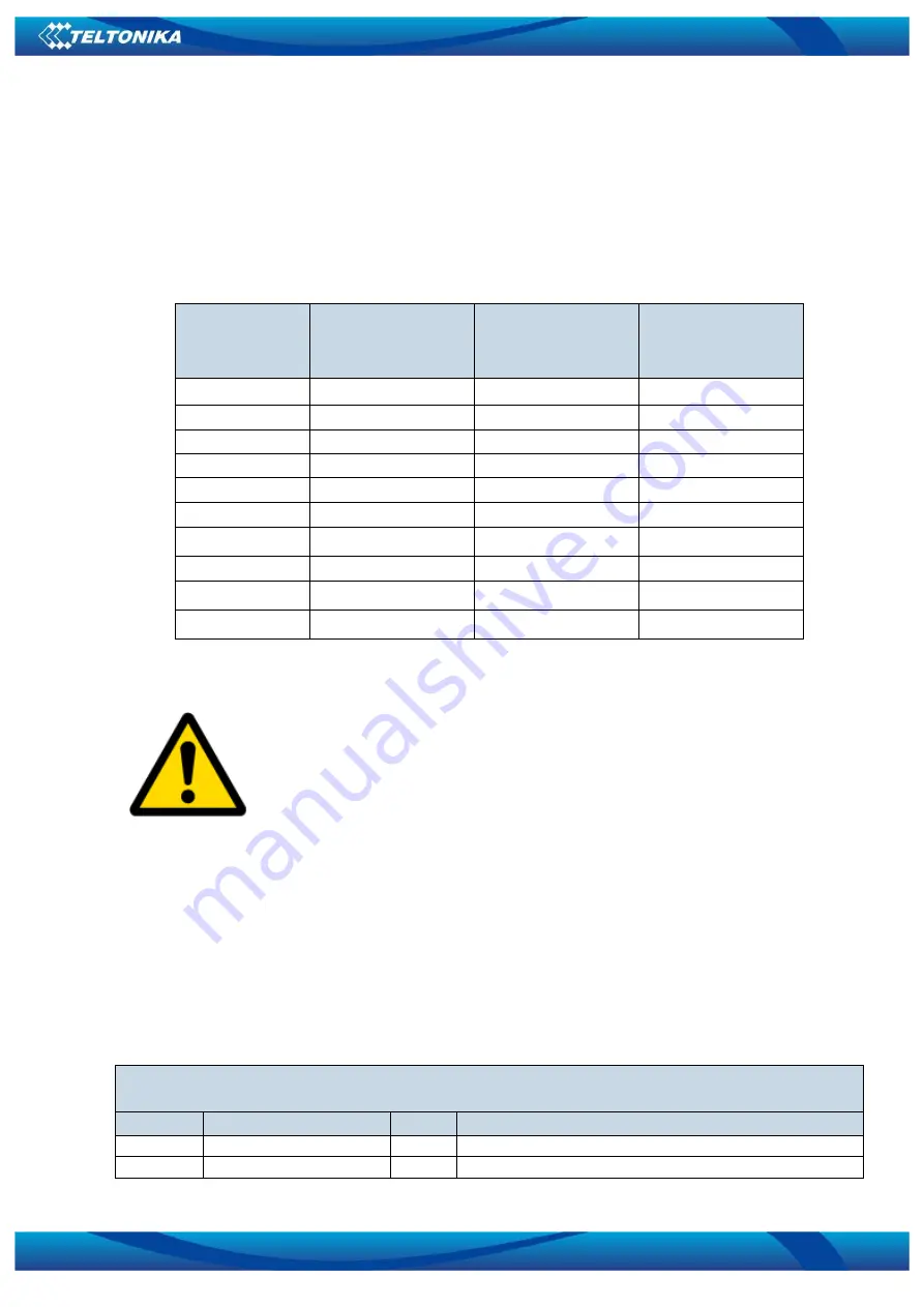
SMS example will configure first profile CAN#0 I/O element with low priority,high level
1,low level 0,logic operand is event on exit,averaging constant is 1,CAN type ID is for 29 bits,output
data mask is 51 and must be written after converting in decimal from binary,CAN ID is for total fuel
used.
The rest CAN elements are configured in the same sequence. CAN elements and parameters
ID’s are listed below.
Table 20 CAN elements and parameters
Manual CAN1
Element
Number
CAN1 Element
parameters
Manual CAN 2
Element
Number
CAN2 Element
parameters
CAN#0
x406
CAN#0
x504
CAN#1
x407
CAN#1
x505
CAN#2
x408
CAN#2
x506
CAN#3
x409
CAN#3
x507
CAN#4
x410
CAN#4
x508
CAN#5
x411
CAN#5
x509
CAN#6
x412
CAN#6
x510
CAN#7
x413
CAN#7
x511
CAN#8
x414
CAN#8
x512
CAN#9
x415
CAN#9
x513
There are only 14 I/O parameters that could use Averaging Constant:
Digital Inputs (1-4); Analog Inputs (1-4); Battery Voltage; Battery Current;
External Voltage; PDOP; HDOP; Speedometer.
I/O parameters: “Current Profile”, “Fuel level meter” (1-2), “Fuel
temperature” (1-2), “GNSS Status”, “Network Type”, “Movement”, “Active
GSM Operator”, “iButton ID”, “Odometer”, “GSM Signal”, “Deep Sleep”,
“Cell ID”, “Area Code”, “PCB Temperature”, “Dallas temperature Sensor
0..2”, “Fuel Counter” and “RFID ID” cannot use Averaging constant
functionality.
6.3.8
I/O
If all I/O elements are disabled AVL packet comes with GPS information only. After enabling
I/O element(s) AVL packet in couple with GPS information contains current value(s) of enabled
I/O element.
6.3.8.1
FMB630 available I/O list
Table 21 PERMANENT I/O elements list description
Permanent I/O elements
(are always sent (with every record) to server if enabled)
Nr.
Property Name
Bytes
Description
1
Digital Input Status 1
1
Logic: 0 / 1
2
Digital Input Status 2
1
Logic: 0 / 1