TELOS 2101 USER’S MANUAL
PART IV
THE STUDIO INTERFACE & ADDITIONAL HYBRIDS
IV-9
SECTION 1 – STUDIO INTERFACE INSTALLATION
1.2
Installation checklist
(Copy this checklist and use it to help organize your installation)
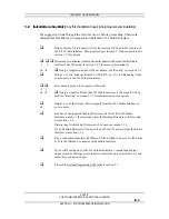
We suggest you look through the rest of section 1 before proceeding. Then work
through this checklist as you prepare to install each 2101 Studio Interface.
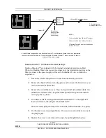
Bring cable for T-Link circuit(s) from the location 2101 hub to the location of
the 2101 Studio Interface. This requires 2 pair for each T-Link connection. See
section 1.3.1 for details.
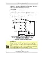
How many mix-minuses (with send-to-caller audio) will be used for this Studio
2 1
Interface? See “Routing” in section 3.3.1 for more on mix-minuses.
È
Æ
If only a single mix-minus will be available, see “Routing” in section 3.3.1.
Bring 1 or 2 mix-minus audio feeds (AES/EBU, or –7 to +4 dBu analog) from
your console to the 2101 Studio Interface.
How many inputs on the console will be used?
2 1
È
Æ
If only a single feed from the 2101 Studio Interface to the console will be
used see “Routing” in section 3.3.1 for information on your options.
Bring 1 or 2 of the Output (Caller) signals from the 2101 Studio Interface to
È
your
console.
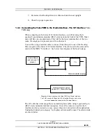
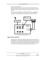
Run one of the supplied Desktop Director cables from the 2101 Studio
Interface to each of the locations where the Desktop Directors will be located.
See
section
1.3.2.
If more than two Desktop Directors will be used see section 1.3.2.
If any Desktop Director will be more than 250 feet (75 meters) from the Studio
Interface see section 1.3.2.
Run a connection from the 10/100Base-T Ethernet hub to be used for the Series
2101 to the 10Base-T connector of the Studio Interface.
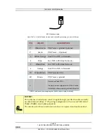
If you will be using any of the 2101 Studio Interface’s remote input/output
options (such as the ringer mute input) to control the unit see section 1.6.1 and
make
those
connections
now.
Proceed to System Programming Checklist in section 2.1.


