TELOS 2101 USER’S MANUAL
PART IV
THE STUDIO INTERFACE & ADDITIONAL HYBRIDS
IV-10
SECTION 1 – STUDIO INTERFACE INSTALLATION
T-Link
Port
T-Link
LOS
LED
1.3
Connections to the 2101 Hub and Extended Hybrid (Telos TWO)
w
IMPORTANT!
Unless otherwise indicated the following instructions apply to both the Series 2101 Studio
Interface and the Telos Extended dual hybrid (Telos TWO Hybrid with special 2101
software). Additional information on the Telos TWO is included in the manual shipped
with that product.
1.3.1
Connecting the 2101 Studio Interface to the 2101 Hub
(Studio Interface only)
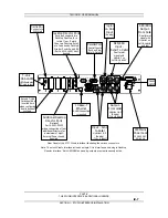
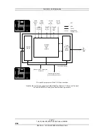
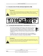
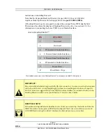
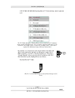
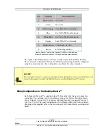
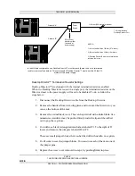
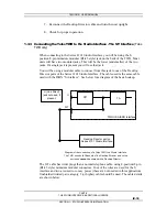
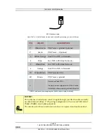
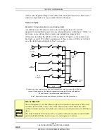
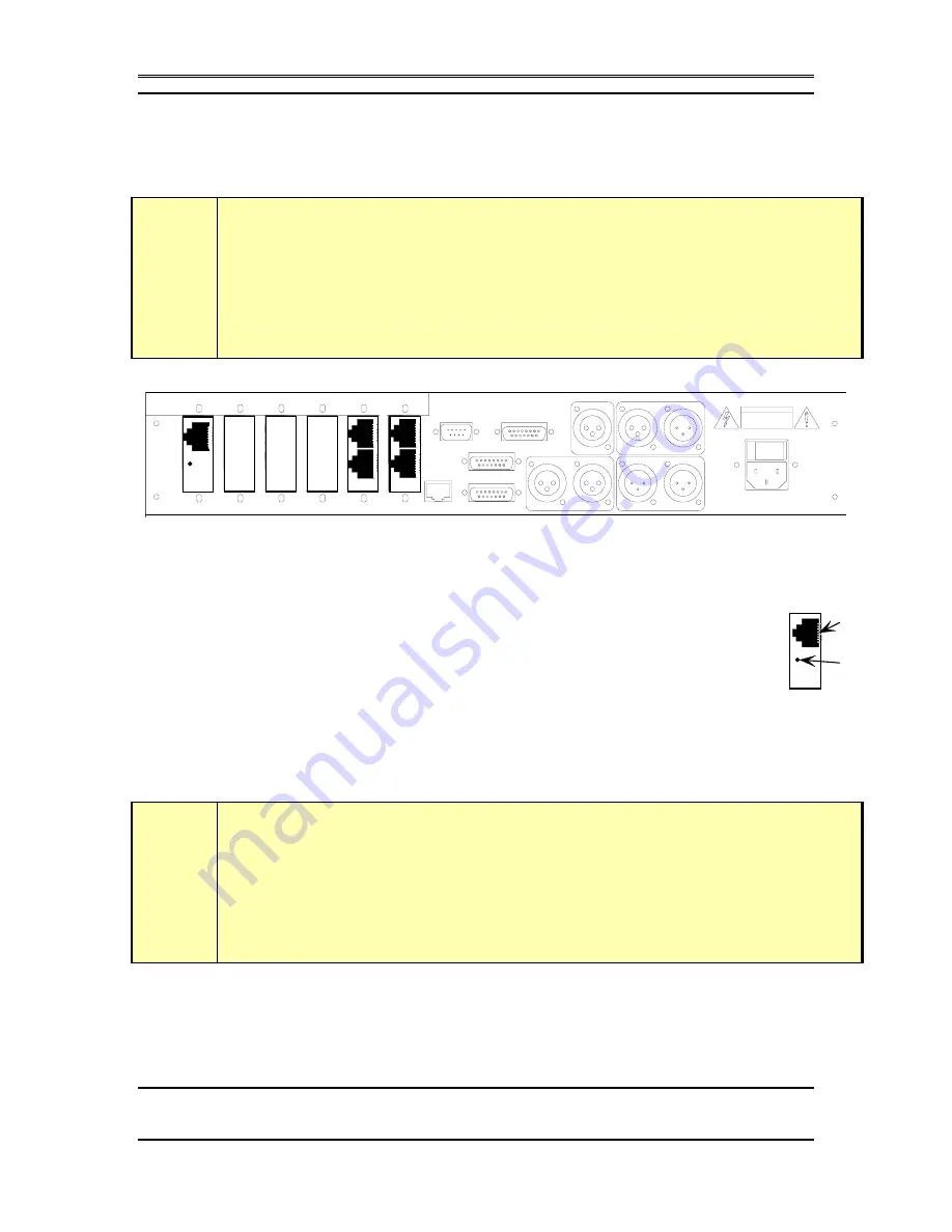
The 2101 Studio Interface uses internal plug-in T-Link module(s) to connect to
the 2101 Hub. These module(s) have a modular jack accessible through each
rear slot, in slots A (or optionally, A& B). This will be a 8 position “RJ-45”
style miniature connector. An amber (yellow) LED next to below this connector
indicates a Loss Of Signal (LOS) and should not be illuminated under normal
circumstances.
The Studio Interface ships with a single module in slot A, if you are building a
redundant system you will need to add a second module (Telos Part # 1701-00048).
Section 4 has information on installing or replacing these modules.
w
IMPORTANT!
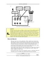
Your T- Link connection(s) are in the first 2 Interface slots from the left side of the unit as
viewed from the rear of the unit (slots A, and optionally, B). The RJ- 45 style connectors to
the right side (slots E & F) are for the Desktop Directors.
1 0
1
2
1
2
A
B
C
D
E
F
RS-232 (DCE)
10 Base-T
SAA 1
SAA 2
Parallel Rem ote
POH
AES/EBU
IN
OUT
IN
1
1
2
2
INPUT- Send to Caller OUTPUT- Caller


