TELOS 2101 USER’S MANUAL
PART IV
THE STUDIO INTERFACE & ADDITIONAL HYBRIDS
IV-37
SECTION 1 – STUDIO INTERFACE INSTALLATION
PIN
FUNCTION
2
Rx (Studio Interface to Computer)
3
Tx (Computer to Studio Interface)
5
Ground
8
CTS (Studio Interface to
Computer)
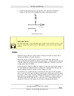
Using a 9 pin D-Sub connector, this is an RS-232 serial port using the standard PC-style
format, configured as if it were a modem.
h
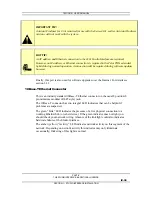
HOT TIP!
This port is configured for DCE (Data Communications Equipment) as opposed to
DTE (Data Terminal Equipment) operation – meaning that it looks like a modem, not
a computer. Therefore, a “reversing” or “null- modem” cable is required to connect to a
modem, while a standard “straight through” cable is required to interface to a
computer. Cables may be easily fabricated or may be obtained from a computer store.
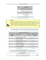
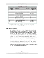
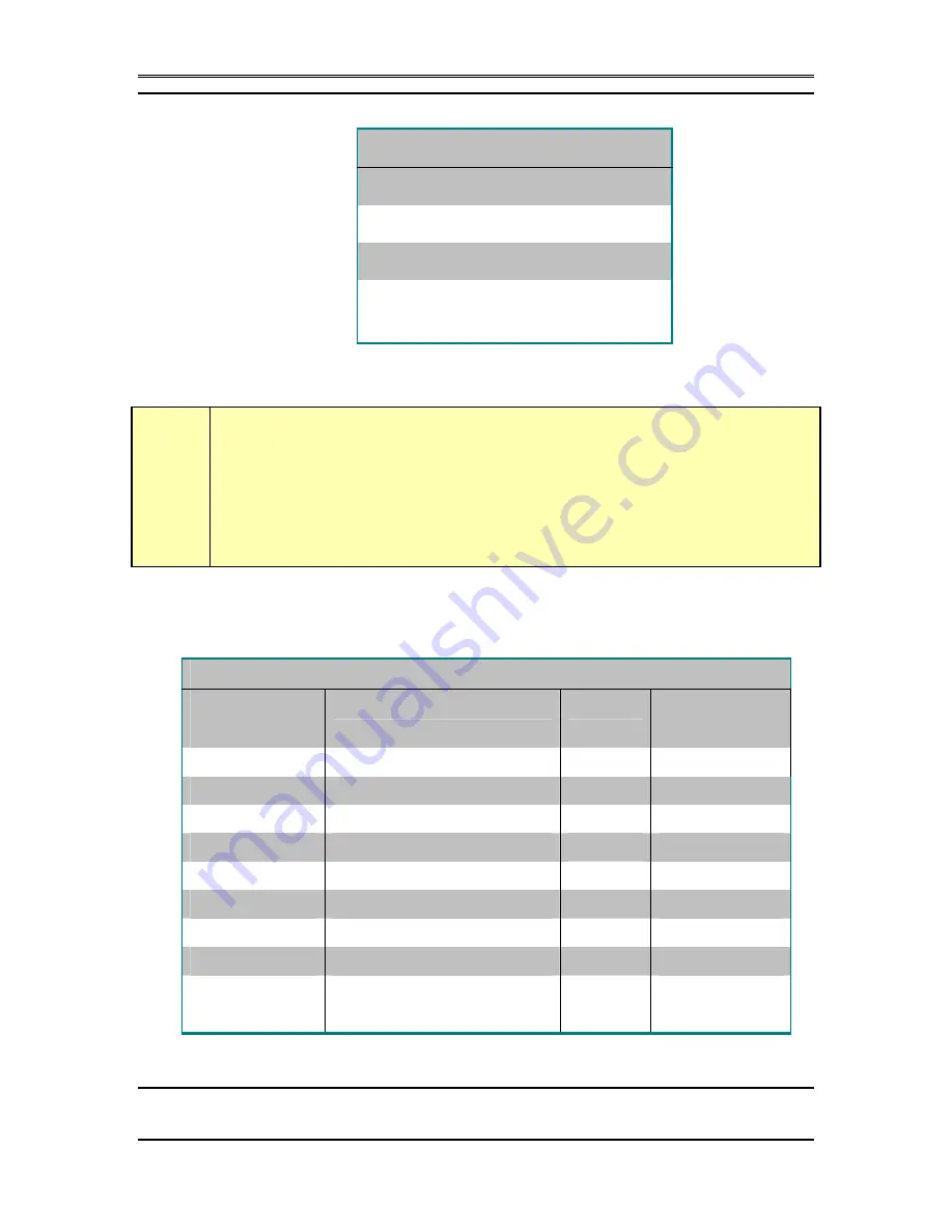
The following tables show the recommended cable configuration for connecting the
2101 Studio Interface or Telos TWO to 9 pin & 25 pin DTE (computer) serial ports.
CABLE PIN OUT 9-PIN
Computer
(DTE)
Description
Direction
Studio Interface
(DCE)
1
*Data Carrier Detect (DCD)
3
8
2
Receive Data (RD)
3
2
3
Transmit Data (TD)
4
3
4
*Data Terminal Ready (DTR)
4
Not used
5
Signal Ground (SG)
5
6
*Data Set Ready (DSR)
3
8
7
*Request to Send (RTS)
4
Not used
8
*Clear to Send (CTS)
3
8
9
*Ring Indicator (RI)
3
Not used
*Optional connection, may not be required
The serial interface only provides one handshake output signal, CTS (on Pin 8). When standard
cables are used it may be necessary to disable “handshaking” or “flow control” in the serial port
setup screen of the software.

