background image


TELOS 2101 USER’S MANUAL 


PART IV 

THE STUDIO INTERFACE & ADDITIONAL HYBRIDS 


 IV-47 


SECTION 2 – STUDIO INTERFACE CONFIGURATION 


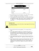
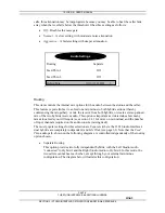
Successful connection to a Show Configuration will be indicated by 
the idle line state on the Desktop Director for each line used in the 
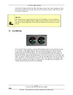
selected Show Configuration. The idle line state looks as follows: 

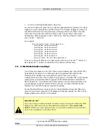
Press the Status button then press the 

6

 button. You should see a 

screen that says Slot A -  Status at the top. If you do not see this screen don’t panic, 
just repeatedly press the 

5

or 

6

 button until you see this screen. 

You should see a screen indicating that an active T-Link connection is present as well 
as statistics on active channels, etc. 

Once you confirmed this we can proceed to make a call and verify that the Studio 
Interface and 2101 Hub are, in fact, working. We will start out with the simplest case, 
a call from your “line 1” to your “line 2”as follows: 


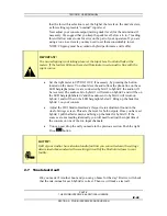
Confirm that the Desktop Director™ you will be using has power and says 
Talent” at the top of the screen. If it says “Producer” follow the directions in 
Part V section 2.1.2 to change this Director to “Talent” mode. 


Choose a Show Configuration using the LCD screen. See Part V section 2.1.3 for 
details on selecting a show. If no show configurations appear check the LAN 
connections at this Studio Interface, 10/100 Base-T LAN hub and the 2101 Hub. 
Check the Telos 2101 hub is running and configured (see Part III). 


First pick up the handset and push the line button in the left row for each line 
active in this Show Configuration, listening for dial tone. If this does not happen 
see Part VI for information on troubleshooting your problem. 


Next, pick up the handset and press the left Line 1 button to select that line for 
dialing. You should now hear  “inside” dial tone on the handset. 


Enter the phone number for line 2 using the numeric keypad of the Desktop 
Director. 


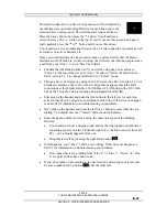
You should now hear a ringing sound and see the ringing Status Symbol (an 
expanding square) on Line 2. Push the right Line 2 button to answer this call. 
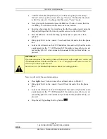
The 

 Icon should appear for line one. 


Drop this test call by pressing the right Drop button 

 . 


If this happens, your “lines” 1 and 2 are working). If this does not happen see 
Part VI for information on troubleshooting your problem. 


Now repeat this test by calling from “Line 2” to “Line 3”, “Line 3” to “Line 
4” etc until all lines have been tested. 


If you do not plan on proceeding to the next section and setting your levels now, 

be sure to push the Drop button 

 after the final call. 


Summary of Contents for 2101 Series

Page 1: ...TELOS 2101 USER S MANUAL TELOS SERIES 2101 AdvancedAllDigitalMulti lineMulti studioBroadcastTelephoneSystem USER S MANUAL PART IV Studio Interface Additional Hybrids V2 0d...

Page 2: ...TELOS 2101 USER S MANUAL PART IV THE STUDIO INTERFACE ADDITIONAL HYBRIDS IV II TABLE OF CONTENTS This blank page is intentional...

Page 3: ...OG AUDIO 27 1 4 3 POH PROGRAM ON HOLD INPUT STUDIO INTERFACE ONLY 29 1 4 4 OUTPUT CALLER LEFT RIGHT AUDIO 29 1 4 5 AES EBU DIGITAL AUDIO IN OUT 30 1 5 AC MAINS POWER 31 1 6 REMOTE CONTROL PORTS 33 1 6...

Page 4: ...NU 69 3 4 EXTERNAL CONTROL 75 3 4 1 RS 232 CONTROL 75 Serial Port Commands Studio Interface only 76 3 4 2 ETHERNET 10BASE T CONTROL 83 3 5 SYSTEM AUDIO PROCESSING AND FEEDBACK CONTROL 83 3 5 1 SEND AU...

Page 5: ...etween 0 to 40 degrees Celsius 32 to 104 degrees Fahrenheit and relative humidity is between 0 to 98 non condensing The unit will operate on any commonly available AC mains voltage between 90 and 240...

Page 6: ...out 2101 Studio Interface includes the following connections 8 Desktop Directors using optional power supplies and expansion card 2 T Link connections to the hub s using optional T Link Studio Interfa...

Page 7: ...or Power Supply Kit Part 0212 1400 must be used Additional Desktop Director Ports Optional Part 2001 00022 allows connection of four additional Directors for a maximum of eight External Power Supply R...

Page 8: ...log 1 SEND to Caller Analog 2 CALLER Out Analog 1 CALLER Out Analog 2 CALLER Out AES 1 2 Ethernet 10 base T WAN LAN Connection Program on Hold Source KEY Data T LINK Analog Audio AES EBU Audio Paralle...

Page 9: ...ur console to the 2101 Studio Interface How many inputs on the console will be used 2 1 If only a single feed from the 2101 Studio Interface to the console will be used see Routing in section 3 3 1 fo...

Page 10: ...a modular jack accessible through each rear slot in slots A or optionally A B This will be a 8 position RJ 45 style miniature connector An amber yellow LED next to below this connector indicates a Los...

Page 11: ...is advisable that precautions be taken to prevent damage caused by power surges Special T1 interface surge protectors can be used to offer some degree of protection at the T Link interface jack If the...

Page 12: ...the left when viewed as above with pins facing you and at the top PIN COLOR 1 White Green 2 Green 3 White Orange 4 Blue 5 White Blue 6 Orange 7 White Brown 8 Brown Not required The T Link connection...

Page 13: ...Ethernet Crossover cable 1 3 2 Desktop Director Connections StudioInterfaceonly The 2101 Studio Interface has 2 Desktop Director ports located in slots F Each port supports 1 Desktop Director directl...

Page 14: ...e from Studio Interface 5 S Receive from Studio Interface 6 S Transmit to Studio Interface 7 Power Sink 8 Power Sink Top The interface connector on the Desktop Director is a standard modular RJ 45 sty...

Page 15: ...tionally a second card can be installed in slot E Pin 1 is at the top Power is provided on pins 7 8 for a maximum of two Desktop Directors If more than one Desktop Director is required on a single por...

Page 16: ...e This connection is limited to 2300 Feet 700 meters and wiring should be configured using the extended passive bus configuration see below for some examples h HOT TIP Since category 5 wire is so comm...

Page 17: ...ower Supply In the extended configuration the Desktop Director must be within 2300 feet 700 meters of the 2101 Studio Interface The power supply must be 250 feet 76 Meters or less from the Desktop Dir...

Page 18: ...rnal termination resistors enabled When two Desktop Directors are used in a single port the termination resistors on the Director closer to the power supply will need to be disabled To do so follow th...

Page 19: ...this jack to one of the Desktop Director ports of the Series 2101 Studio Interface The cable used is the same cable used with the ISDN S interface See below for a diagram of the basic hookup U S T NT1...

Page 20: ...Blue Rcv NT1 to TE from Network 6 Orange Xmt TE to NT1 to Network 7 White Brown PS 2 Power 48 VDC 8 Brown PS 2 Power ground Not used on Telos TWO Used only in units shipped to the USA Canada Not need...

Page 21: ...both the Series 2101 Studio Interface and the Telos TWO dual hybrid Additional information on the Telos TWO is included in the manual shipped with that product 1 4 1 Mix Minus What is a mix minus The...

Page 22: ...to Utility as well just never the fader representing the hybrid s own audio LINE CHANNELS UTILITY BUS PROGRAM BUS PHONE CHANNEL PROGRAM OUT Send Rcv Hybrid MICRO PHONES A typical mix minus using an e...

Page 23: ...lly off for the input channel with the caller audio Mic Preamp AUX 1 AUX 2 OUTPUT FROM HYB 1 LEFT OUTPUT RI GHT OUTPUT AUX 1 OUT AUX 2 OUT TO HYB 1 IN UTILITY MIXER Mic1 Caller NOTE This must be turne...

Page 24: ...the mic preamp output directly to the hybrid as well to the board mixer console mixing desk This approach lacks flexibility and requires additional equipment if more than one mic is used and or more...

Page 25: ...st place to look when strange or erratic performance is experienced The quickest test is to bring up only the hybrid in question on the board and select a line Dial tone should not appear on the send...

Page 26: ...y If the hybrid isn t doing a good job of preventing the send audio from leaking to its output the special remote send mix minus is corrupted Remember if any of the announcer audio from the remote sit...

Page 27: ...s Remote Mix Minus Studio Console Other Sources for music etc Zephyr Trans mission Path Phone Hybrid REMOTE SITE STUDIO Microphone Talent Headset Diagram showing system set up for remotes with delay i...

Page 28: ...se a decrease in hybrid performance Some consoles with high amounts of headroom may cause clipping A 10 dB pad will help in these cases h HOT TIP The signal fed to these inputs should be a mix minus o...

Page 29: ...puts Clipping point is 18dBu 4 dBu nominal input h HOT TIP You do not need to provide a Program on Hold source to the optional Telos TWO Hybrid The Program on Hold source fed to the Studio Interface w...

Page 30: ...o Hybrid 1 while the right input will be fed to Hybrid 2 the internal routing of these two signals can be changed using the Routing option in the Audio menu Because of this fact you may need an extern...

Page 31: ...nd more information about setting the AES Out sync modes in section 3 3 1 1 5 AC mains Power The AC receptacle connects mains power to the unit with a standard IEC International Electrotechnical Commi...

Page 32: ...32 SECTION 1 STUDIO INTERFACE INSTALLATION w IMPORTANT SAFETY INFORMATION If fuse replacement is required please note For continued protection against fire replace fuse only with same type and value S...

Page 33: ...ding device The pin outs and interface specifications are given here The available functions for these inputs and outputs are Record Control Outputs See Part V section 2 3 3 for more information Ring...

Page 34: ...ed current on these pins to 400mA could cause hardware damage or system instability CURIOSITY NOTE The DB designation for D Sub connectors is from Cinch Corp s part numbering system The proper Cinch d...

Page 35: ...equipment has the pull ups built into their control inputs check the device s manual to be sure If there is no pull up in the interfaced equipment you ll have to add one An appropriate value is 2 2K C...

Page 36: ...ts DC on pin 3 has both SAA ports in parallel with pin 8 on the Parallel remote control port Failure to limit the combined current on these pins to 400mA could cause hardware damage or system instabil...

Page 37: ...gh cable is required to interface to a computer Cables may be easily fabricated or may be obtained from a computer store The following tables show the recommended cable configuration for connecting th...

Page 38: ...his allows the Studio Interface to communicate with the Series 2101 Hub This connection is required for the system to operate The Series 2101 uses IP Internet Protocol for its communications Therefore...

Page 39: ...ades over the Internet For details see section 3 3 3 10 Base T Ethernet Connector This is an industry standard 10Base T Ethernet connector on the usual 8 position 8 pin miniature modular RJ 45 style j...

Page 40: ...TELOS 2101 USER S MANUAL PART IV THE STUDIO INTERFACE ADDITIONAL HYBRIDS IV 40 SECTION 1 STUDIO INTERFACE INSTALLATION Blank blank blank I tell you this page is blank This writing It does not exist...

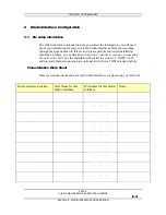
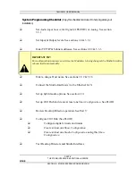
Page 41: ...g through the steps outlined in this section please perform the initial installation hooking up cables etc as described in section 1 with the exception of connecting the units to the LAN See the Insta...

Page 42: ...guration purposes every time the IP address Is being changed the Studio Interface reboots Itself automatically R Enter a unique Host name See sections 2 2 2 3 3 3 R Connect the Studio Interface s to t...

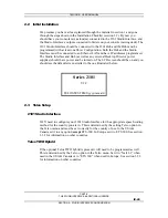
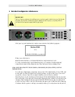
Page 43: ...s well as any external Desktop Director power supplies should have power and be turned on The LCD screen should be on and you should see the default screen similar to the one illustrated below Series...

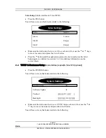
Page 44: ...ect button Press the 5 button until the appropriate protocol is shown and press the Select button again to confirm See section 3 3 2 for additional information on the correct choice 2 4 TCP IP Hostnam...

Page 45: ...nterface reboots Itself automatically Move the dark cursor bar to IP Addr using the 6 key and press the Select button Enter a subnet mask using the numeric keys You should consult with your network ad...

Page 46: ...back up use the 5 button As usual the Select button confirms entry 2 5 Is this Studio Interface working You will need to make sure the 2101 Hub is up and running first See Part III The System Hub for...

Page 47: ...he LCD screen See Part V section 2 1 3 for details on selecting a show If no show configurations appear check the LAN connections at this Studio Interface 10 100 Base T LAN hub and the 2101 Hub Check...

Page 48: ...e hybrids are TURNED OFF w IMPORTANT If your board operators typically run in the red you should do the same We ve said this twice since clipping on the hybrid s inputs must be avoided or hybrid perfo...

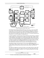
Page 49: ...these LED bargraphs since we are connected hybrid 1 to hybrid 2 the audio will be reversed The audio sent to hybrid 1 will return on hybrid 2 and will be on the LED bargraph labeled 2 and the audio se...

Page 50: ...at the left meter on the 2101 Studio Interface and verify that this audio is not present on the 1 LED bargraph If this audio is present here you are not feeding hybrid 1 a mix minus and you must fix...

Page 51: ...how If no show configurations appear check the LAN connections at this Studio Interface 10 100 Base T LAN hub and the 2101 Hub Check the Telos 2101 hub is running and configured see Part III 3 Makes s...

Page 52: ...io Interface and decide how to set up the following parameters Desktop Director Operation Talent mode Vol 3 Part V Section 4 Desktop Director Operation Producer Mode Vol 3 Part V Section 3 Receive EQ...

Page 53: ...Status button to display these A few words about the 2101 Studio Interface Extended Hybrid Telos TWO and their hardware family You will note a high degree of similarity between the 2101 Studio Interfa...

Page 54: ...e here to help 3 1 Level Metering The Telos 2101 Studio Interface and Telos TWO hybrid include two dual LED dual meters As is customary with digital equipment these are peak reading meters with the to...

Page 55: ...section 2 4 for step by step instructions and section 3 3 1 for more information on setting this level So what s the difference between Studio In level and Hybrid send level Well we re glad you asked...

Page 56: ...ering includes a peak level function The LED segment indicating the peak level remains on for approximately one second holding the peak value 3 2 Status Displays Pressing the Status button displays th...

Page 57: ...value of the setting When you reach the value you desire press the Select button again to lock it in and return you to the item selection scroll mode 3 3 1 The Audio Menu This group consists of sixte...

Page 58: ...ge of 4 to 2 dB Send Eq Turning on this equalizer simulates the audio response of a telephone handset microphone and will improve intelligibility Sometime high quality microphones sound too good and t...

Page 59: ...ived caller audio to be attenuated ducked when the announcer speaks This is often desired for aesthetic effect and allows the announcer to remain in control of the conversation Permits open loudspeake...

Page 60: ...d This is a simple manual equalizer mode where EQ values selected for LF and HF are applied constantly Adaptive Dynamic Digital This is a three band dynamic equalizer The proper values of high and low...

Page 61: ...ng them together or mix the receive from both hybrids or create a stereo panned mix of the two hybrids receive audio This option is important as it determines how many mix minus feeds you will require...

Page 62: ...id 1 and hybrid 2 as completely independent hybrids The only correlation between the two are the input and output gain levels and certain other options that control both hybrids The audio paths howeve...

Page 63: ...of this cross feed path See diagram below The Mix Panned gives a stereo output with the two callers panned to either side Each caller hears a mix of the two studio audio inputs plus any caller on the...

Page 64: ...ar one another through the hybrid The hybrid mix control in the Audio menu determines the level of this cross feed path See below The Mix Mono routing option provides identical audio with both callers...

Page 65: ...be able to hear one another through the hybrid The hybrid mix control in the Audio menu determines the level of this cross feed path The Mix Wide routing option gives independent caller audio outputs...

Page 66: ...d Mix This option allows adjustment of the amount of cross feed of one hybrid s output to the other The range is from 12 to 8 0 represents no gain or loss between callers and is the usual setting If y...

Page 67: ...lephone network in your country Note that the items for Slot A Slot B Slot C Slot D will say T Link or EMPTY depending on how your system is configured Audio Settings Telco Natl I 1 Slot A T Link Slot...

Page 68: ...s Brazil Costa Rica Mexico A Law Set to ETS 300 Americas Canada Dominican Republic Puerto Rico United States of America Venezuela u Law Set to any option but ETS 300 Europe Belgium Czechoslovakia Fran...

Page 69: ...Series 2101 Studio Interface only Your T Link cards are in slots A B A card will only be present in slot B only if you have added an optional second card When the system is turned on it scans the slo...

Page 70: ...a period As usual the 5 key will backspace if you make a mistake or need to delete an old entry Hostname Studio Interface Only You must assign a unique name to each Studio Interface Allowable charact...

Page 71: ...internet service provider This is a numeric only field enter the digits as described above DNS IP This is the IP address of the DNS Domain Name Server you will be using It is an IP address just as wi...

Page 72: ...at you prefer the original software This allows you to compare the two versions and determine which version better meets your needs Update software This menu brings up a query window which asks Are yo...

Page 73: ...n this protects you from deleting your primary bank software unless the downloaded software is capable of successfully operating h HOT TIP If you get the error Cannot perform operation from this bank...

Page 74: ...to 20 Click Volume Adjusts the volume of the audible click generated when a front panel button is pressed The value 0 is off and 20 is loudest quite loud in fact We prefer settings from 0 to 5 Serial...

Page 75: ...n is for the rare case where Telos Customer Support may require you to do so First connect the Studio Interface to a computer s serial port Since the Studio Interface has a DCE interface you will need...

Page 76: ...tion are very powerful and can interfere with normal operation of the Studio Interface if used incorrectly Please note that you should avoid using a command that you do not understand Note also that t...

Page 77: ...ber base is 16 Line editing commands are R repeats last command L K recall previous commands S and D move cursor one character left or right A and F move cursor one word left or right X deletes charac...

Page 78: ...External Name AudOutGain Parameter AudOutGain value Description Set Audio output gain to value Name AudDplx Parameter AudDplx level Description Display duplex level or set to level Name AudAGC Parame...

Page 79: ...dAdapt Parameter AudStudAdapt value Description Display current Studio Adapt setting or set to value Name AudBurst Parameter AudBurst 0 1 Description Display Adapt Burst setting or change to 0 off 1 o...

Page 80: ...ite Parameter FTPsite site Description Display or change FTP site Name IPdns Parameter IPdns DNS Description Display or change DNS server Name IPgw Parameter IPgw gateway Description Display or set ga...

Page 81: ...iven director Name LnTelco Parameter LnTelco switch Description Display current switch type and options or set switch type Name LnSet Parameter LnSet Description Display current line settings by card...

Page 82: ...reator 21 HDLC Msg Parser 22 HDLC Buffer 23 NonVolatile 24 Storage Manager 25 Storage Man Proxy 26 StorMan Pxy Helper 27 Application 28 App Messages 29 App Threads 30 Services 31 Service Thread 32 App...

Page 83: ...o processing consists of the following functions Sample rate conversion High pass filter Frequency shifter Send equalizer Send AGC Limiter Sample Rate Conversion AES EBU sources are sample rate conver...

Page 84: ...e low frequency audio they pick up can sound unnatural on a telephone handset Equalisation Characteristics of the Send EQ Send Automatic Gain Control Limiter This AGC helps maintain consistent audio l...

Page 85: ...resent And reduces low level leakage thereby improving hybrid performance This function is cross coupled with the AGCs and the duplex system Digital Dynamic Equalizer Telephone audio frequency respons...

Page 86: ...speaking this loss is inserted in the announcer path when the announcer is speaking the loss is inserted in the caller gain is reduced The effect is somewhat seesaw like with the total loss always bei...

Page 87: ...g the mics or speakers It also helps of course to use directional mics Customers have reported good results with cardioid mics such the EV RE 20 and the Shure SM 7 Add equalization to the monitor path...

Page 88: ...TELOS 2101 USER S MANUAL PART IV THE STUDIO INTERFACE ADDITIONAL HYBRIDS IV 88 SECTION 3 STUDIO INTERFACE DETAILED CONFIGURATION REFERENCE This page left devoid of useful information intentionally...

Reviews: