TELOS 2101 USER’S MANUAL
PART IV
THE STUDIO INTERFACE & ADDITIONAL HYBRIDS
IV-20
SECTION 1 – STUDIO INTERFACE INSTALLATION
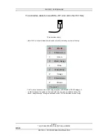
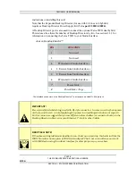
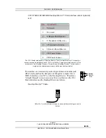
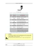
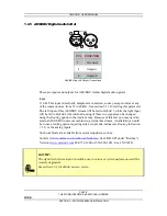
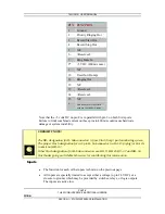
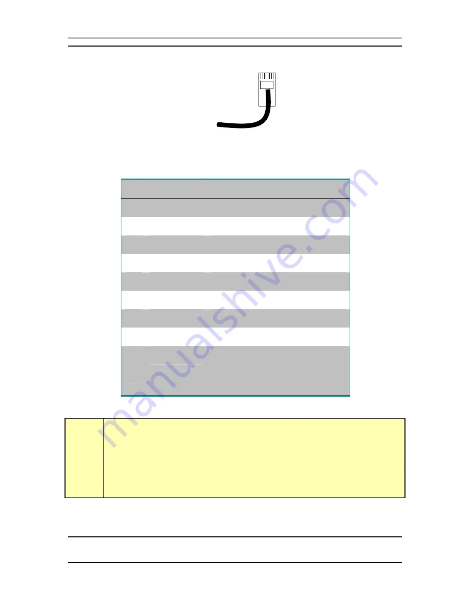
BRI S Interface cable.
Note: Pin 1 is to the left when viewed as above (with pins facing you and at the top).
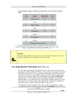
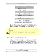
PIN
COLOR
DESCRIPTION
1*
White/Green
PS 3 Power +/ground (Optional)
2*
Green
PS 3 Power – (Optional)
3
White/Orange Xmt (TE to NT1) to N
4
Blue
Rcv (NT1 to TE) from N
5
White/Blue
Rcv (NT1 to TE) from Network -
6
Orange
Xmt (TE to NT1) to Network -
7@
White/Brown
PS 2 Power 48 VDC -
8@
Brown
PS 2 Power +/ground
*
@
Not used on Telos TWO
Used only in units shipped to the USA & Canada.
Not needed when connecting to Studio Interface
ISDN S interface cable wiring diagram. Both ends are wired identically.
h
HOT TIP!
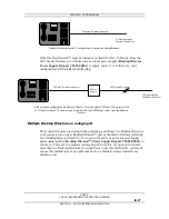
This cable has 4 twisted pairs wired “straight through” just like the cable normally
used for Ethernet 10 Base- T. The wiring configuration is the same as TIA/E- 568- A
T568A (T568B is electrically equivalent).
The outside pairs (Brown and Green) are often not required and may be omitted.

