Models 707B and 708B Switching Matrix Reference Manual
Appendix A: Maintenance
707B-901-01 Rev. B / January 2015
A-5
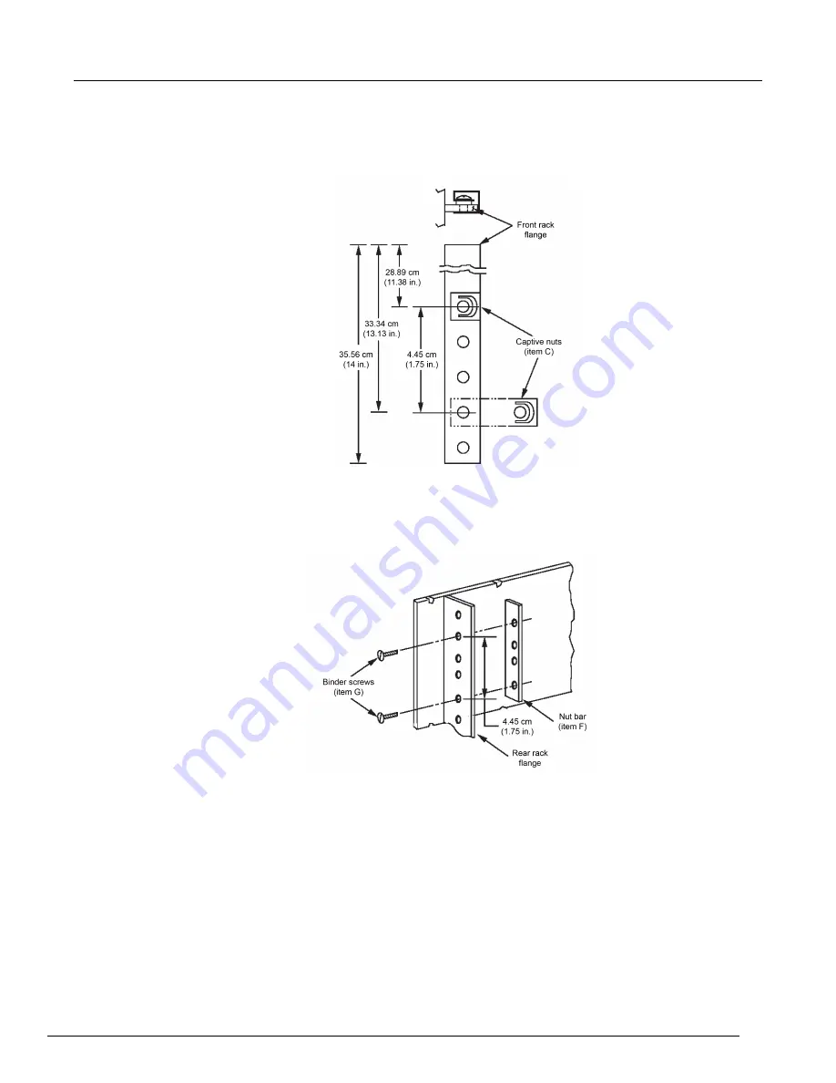
2. As shown in the following figure, install two captive nuts (item C) on each front rack flange at
holes 28.89 cm (11.38 in.) and 33.05 cm (13.13 in.) from the top of the selected space.
Figure 101: Captive nut installation
3. Loosely attach a nut bar (item F) to each rear rack flange with two binder head screws (item G)
(see the following figure). Mount the nut bars with the outer holes at the same level as the captive
nuts. Note that the hole pattern on the nut bar is not symmetrical.
Figure 102: Nut bar on flange


