


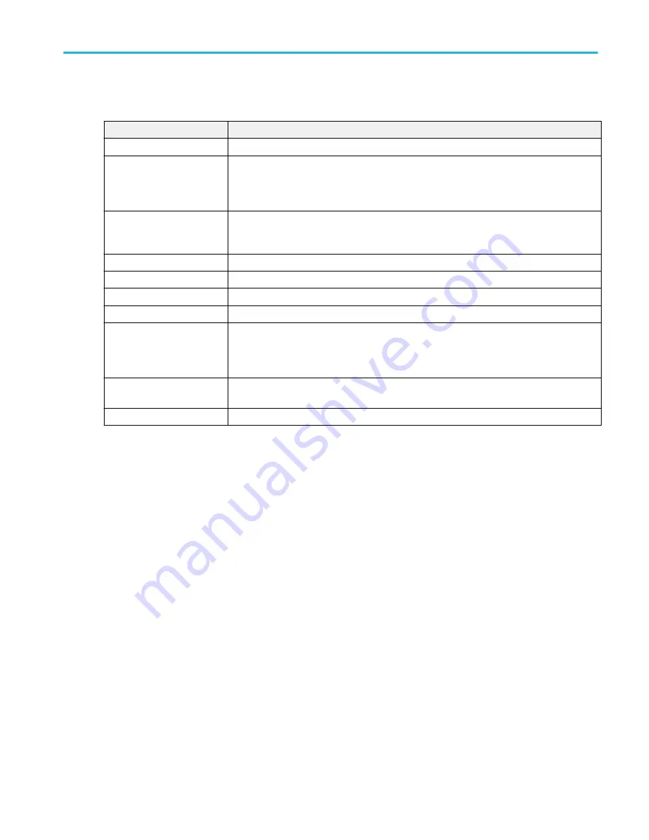
I2C serial bus menu fields and controls.
Field or control
Description
Display
Turns on or off displaying the bus on the Waveform view.
Label
Enter a label for the bus. The default label is the selected bus type.
To enter label text, double-tap the field and enter label using the virtual keyboard, or tap the
field and enter text from an attached keyboard.
Position
Sets the vertical position of the bus waveform. The default position is vertically centered in a
slice (in Stacked mode), or center screen in Overlay mode. The unit of position is screen
divisions.
Set to 0
Sets the vertical position to 0 divisions (centered vertically in a slice or on the screen.
Bus Type
Set to I2C.
SCLK Input
Sets the source and threshold level for the Serial Clock Line signal.
SDA Input
Sets the source and threshold level for the Serial Data signal.
Include R/W bit in Address
Select Yes to display 7-bit addresses as eight bits, where the eighth bit (LSB) is the R/W bit, or
display 10-bit addresses as 11 bits, where the third bit is the R/W bit.
Select No to display 7-bit addresses as seven bits, and 10-bit addresses as ten bits.
Display Format
Sets the waveform view to show just the decoded bus information, or the decoded bus plus the
source signal waveforms.
Decode Format
Sets the decode format used to display the bus information. Formats are Hex and Binary.
Other bus types. Other serial bus types, such as CAN, LIN, SPI, FlexRay, and so on, are available as purchasable options.
Once purchased and installed, the new bus types are shown in the Bus Type menu. The serial bus options also add
corresponding bus trigger capabilities to the Trigger menu.
on page 192
Audio serial bus configuration menu
on page 194
CAN serial bus configuration menu
on page 196
on page 198
FlexRay serial bus configuration menu
on page 200
LIN serial bus configuration menu
on page 204
Parallel Bus configuration menu
SENT serial bus configuration menu
on page 211
SPI serial bus configuration menu
SPMI serial bus configuration menu
on page 215
USB serial bus configuration menu
on page 217
Menus and dialog boxes
MSO54, MSO56, MSO58, MSO58LP, MSO64 Help
203
Summary of Contents for 6 series
Page 24: ...Product documents and support 4 MSO54 MSO56 MSO58 MSO58LP MSO64 Help ...
Page 42: ...Options 22 MSO54 MSO56 MSO58 MSO58LP MSO64 Help ...
Page 54: ...Install your instrument 34 MSO54 MSO56 MSO58 MSO58LP MSO64 Help ...
Page 84: ...Getting acquainted with your instrument 64 MSO54 MSO56 MSO58 MSO58LP MSO64 Help ...
Page 102: ...Configure the instrument 82 MSO54 MSO56 MSO58 MSO58LP MSO64 Help ...
Page 148: ...Advanced triggering 128 MSO54 MSO56 MSO58 MSO58LP MSO64 Help ...
Page 154: ...Zooming on waveforms 134 MSO54 MSO56 MSO58 MSO58LP MSO64 Help ...
Page 438: ...Waveform acquisition concepts 418 MSO54 MSO56 MSO58 MSO58LP MSO64 Help ...
Page 448: ...Waveform display concepts 428 MSO54 MSO56 MSO58 MSO58LP MSO64 Help ...
Page 518: ...Index 498 MSO54 MSO56 MSO58 MSO58LP MSO64 Help ...


