3. INSTALLATION PROCEDURE FOR THE OPTIONAL EQUIPMENT
EO18-33011
3.1 PCMCIA PC BOARD
3- 2
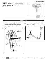
Fig. 3-2
SMW-3x6 Screw
5) Attach the enclosed locking support to the CPU PC board. Connect CN100 on the PCMCIA PC
board to CN7 on the CPU PC board directly, and put them together with the locking support.
6) Secure the PCMCIA PC board to the two PCB attachment plates with the enclosed SMW-3x6
screws.
7) After installing the PCMCIA PC board, reassemble the printer in the reverse order of removal.
PCMCIA PC Board
CN7
CN100 (Solder Side)
Locking Support
PCB Attachment Plate
CPU PC Board