37
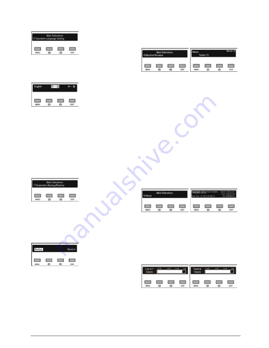
2.1.4.6 Operation language setting
Select LCD display language from simplified Chinese,
Traditional Chinese and English. Other languages can
be added by the user through LCD_Designer tool.
Select language:
a). Press the “
/
” button to select LCD display
language;
b). Press the “MENU” button to save and return to the
upper level menu.
2.1.4.7 System parameter backup/restore
If USB feature is enabled, system parameters can be
backed up or restored through the front panel USB port.
Make sure that the USB disk is properly connected;
otherwise it will prompt “Please insert the USB disk.”.
a). Press the “
/
” button to select “Backup” or
“Restore”;
If “
Backup
” is selected, system parameters can
be backed up;
If “
Restore
” is selected, system parameters can
be restored;
b). Press the “MENU” button to confirm and to go to the
selected menu item;
c). Return to the upper level menu after backup or
recovery.
2.1.4.8 Machine rename
Set alias for the HCS-4100M/50 with a maximum
length of 16 characters or less. It is convenient to
identify them on the operation of room combiner.
a). Press the “MENU” button to enter the name setting
interface, the cursor blinks under the first character;
b). Press the “
/
” button to move the cursor;
c). Press the “MENU” button to modify the character;
Press the “
” button to clear all the characters
after the cursor;
press the “
” button to select the new character;
d). Press the “MENU” button to save at each
character;
e). Press the “EXIT” button to return to the upper level
menu after setting finished.
2.1.4.9 About
CMU information includes: firmware version,
corporation information and series number, shown as
in the following figure - press any button to return to the
upper level menu.
2.1.4.10 Volume control
Volume can be adjusted by volume knob on the CMU
front panel - LINE IN 1 VOL. adjust knob and MASTER
VOLUME adjust knob. Meanwhile, the corresponding
volume indicator will be displayed on the LCD, as
shown in the following figure:
Summary of Contents for HCS-4100MA/50
Page 50: ...35 Figure 2 1 10 Floor mode setting Normal Mode Figure 2 1 11 Floor mode setting Insert Mode...
Page 51: ...36 Figure 2 1 12 Floor mode setting Sync Line Out1 Mixer...
Page 67: ...52 Figure 3 2 6 Installation diagram of HCS 48U6SPK...
Page 80: ...65 Figure 3 3 3 Cutout of HCS 48U8 series flush mounted congress unit unit mm...
Page 81: ...66 Figure 3 3 4 Cutout of HCS 48U9 series flush mounted congress unit unit mm...
Page 82: ...67 Figure 3 3 5 Cutout of HCS 48U7MICSPK flush mounted congress unit unit mm...
Page 85: ...70 Figure 3 3 8 Installation of HCS 48U7MICSPK series flush mounted congress unit...
Page 100: ...85 3 4 2 Installation Figure 3 4 2 Cutout of HCS 48U10 series congress unit unit mm...
Page 101: ...86 Figure 3 4 3 Installation of HCS 48U10 series congress unit...
Page 162: ...147 3 10 2 Installation Figure 3 3 2 Installation of HCS 4851 50 series congress unit unit mm...
Page 163: ...148 Figure 3 3 3 Installation of HCS 4851 50 series congress unit...
Page 181: ...166 Figure 3 12 3 Installation of HCS 4325U 50 congress unit unit mm...
Page 196: ...181 Figure 3 13 7 Multi function connector connected to the HCS 4341 50 series congress unit...
Page 212: ...197 Figure 3 14 18 Multi function connector connected to HCS 4841 42 43 series congress units...
Page 225: ...210 3 16 2 Installation Figure 3 16 2 Installation of HCS 1080 electronic nameplate...
Page 275: ...260 HCS 1020 clip microphone...
Page 316: ...301 Appendix Custom made cable Appendix Dedicated 6 PIN Extension Cable...


