OnAir 1500 Digital Mixing Console
Operating Elements 4-3
Document generated: 06.08.14
SW V6.0
4
OPERATing ElEmEnTs
4.1 Fader section
Overload
Ch Active
Channel
ON / OFF
(or Ch ON only
with Setup 2)
*
PFL
(or Ch OFF
with Setup 2)
*
100 mm
Fader
Talkback
(or CUE / TB
with Setup 2)
*
Select
Ch Assign
Record
OLED
Display
Rotary
Encoder
+ Key
*
Alternate snap-on key
caps are contained in the
spare parts kit shipped
with the console.
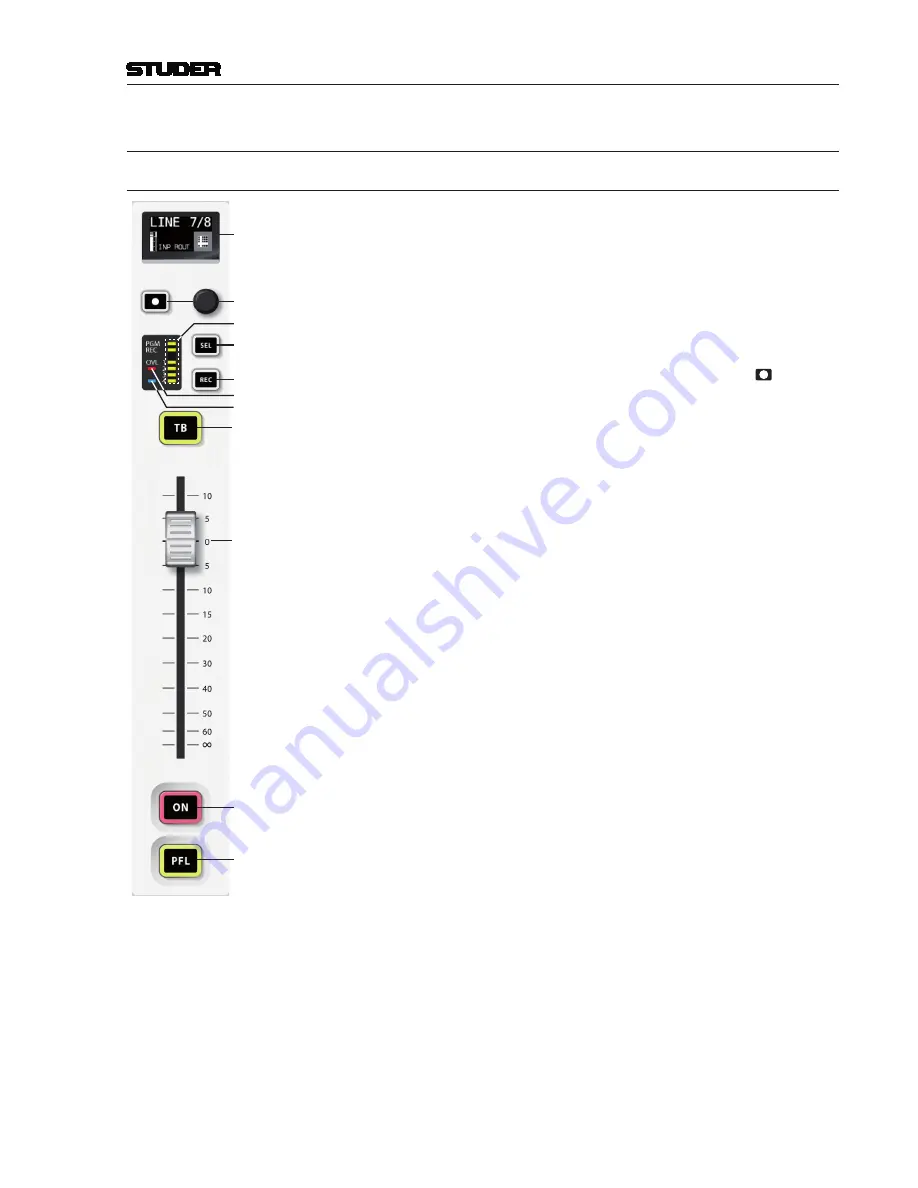
The fader section with the OLED (organic LED) display contains six fader
strips
(only one of them shown in the illustration on the left; approx. 60%
original size)
. The fader strip has been designed with a minimum of operating
elements. Parameter settings are ava ilable through the new feature nicknamed
‘Mini Vistonics’ or via an external screen, mouse and keyboard. Rarely used
and system administration functions (such as system configuration) can be
accessed via the external elements only. These are normally connected to the
console only if used.
Every fader strip contains 3 large keys the functions of which depend on
the selected setup, the fader, a rotary encoder with associated key, and a
graphical OLED channel label display.
There is an additional indicator field with a red overload LED, six yellow
LEDs for channel assignment indication, and a blue channel-active LED. A
channel is considered as ‘active’ if it is switched ON, its fader is open, this
channel is assigned to a master bus, and the master control is open.
*
The large keys have snap-on caps for convenient labeling. This allows for
example to have
ON
and
OFF
keys at the lower end of the channel strip if
required, or to assign a different function such as fader start to the
TB
key
if the source is e.g. a CD player. These settings are input source-related
and will automatically follow the source in case the routing is changed.
The illustration at the left shows the factory default key labeling. Alternate
key caps are contained in the console’s spares kit.
ON
Pressing the key toggles the channel on/off function (default configuration).
In the audio path, the on/off switch is located
after
fader and panning. On
status is indicated by illuminating the key.
*
This key may also be a channel
ON
only key (if setup 2 is active).
Channel on/off is disabled if the channel strip is configured as master fader.
PFL
The purpose of
PFL
(‘pre-fader listening’) is to feed the pre-fader audio signal
of the desired channel, AUX send or master (program, record) to the PFL bus.
If active, the key is illuminated in yellow.
If the ‘PFL Cut on Channel Active’ function (also referred to as ‘broadcast
PFL mode’) is enabled, audio signals are temporarily cut from the PFL bus
as long as the channel is
ON
and the fader is open. In such a case the
PFL
key
is illuminated in amber.
*
This key may also be a channel
OFF
key (if setup 2 is active).
TB
For N–X owner channels, this key’s function is
TB
(talkback) to the N–X
bus. If more than one owner is configured to the same N–X output, all cor-
responding
TB
keys work in parallel.
*
This key may also be a
CUE/TB
key (if setup 2 is active). The purpose of
CUE
is to feed the after-fader, after-pan and pre-on/off audio signal of the
corresponding channel to the PFL bus.
CUE
is activated/deactivated by a
short press of the key, it is illuminated in yellow if active. When pressing
and holding the key,
TB
is activated, and canceled upon release; the key
is illuminated in red. If the key is pressed and held while
CUE
is already
active, the key colour changes to amber.
REC
The
REC
function is used to assign the channel signal directly to the record
bus, regardless of the fader position, the
ON
key, and the bus assignment. If
active, the key is illuminated in red.
Summary of Contents for OnAir 1500
Page 1: ...Studer OnAir 1500 Digital Mixing Console SW Version 6 0 Operating Instructions ...
Page 18: ...OnAir 1500 Digital Mixing Console 1 2 Introduction Date printed 06 08 14 SW V6 0 ...
Page 24: ...OnAir 1500 Digital Mixing Console 1 8 Introduction Date printed 06 08 14 SW V6 0 ...
Page 26: ...OnAir 1500 Digital Mixing Console 2 2 General Date printed 06 08 14 SW V6 0 ...
Page 35: ...OnAir 1500 Digital Mixing Console General 2 11 Date printed 06 08 14 SW V6 0 ...
Page 37: ...OnAir 1500 Digital Mixing Console 3 2 Setup Date printed 06 08 14 SW V6 0 ...
Page 43: ...OnAir 1500 Digital Mixing Console 3 48 Setup Date printed 06 08 14 SW V6 0 ...
Page 45: ...OnAir 1500 Digital Mixing Console 4 2 Operating Elements Document generated 06 08 14 SW V6 0 ...
Page 56: ...OnAir 1500 Digital Mixing Console Operating Elements 4 13 Document generated 06 08 14 SW V6 0 ...
Page 219: ...OnAir 1500 Digital Mixing Console Operation 5 163 Document generated 06 08 14 SW V6 0 ...
Page 223: ...OnAir Digital Mixing Consoles 6 4 Configuration Document generated 06 08 14 SW V6 0 ...
Page 372: ...OnAir Digital Mixing Consoles Configuration 6 153 Document generated 06 08 14 SW V6 0 ...
Page 374: ...OnAir 1500 Digital Mixing Console 9 2 Networking Document generated 06 08 14 SW V6 0 ...
Page 386: ...OnAir 1500 Digital Mixing Console 9 14 Networking Document generated 06 08 14 SW V6 0 ...


