5.1.2 TZLX-Series Tape Drive/Shelf Locations
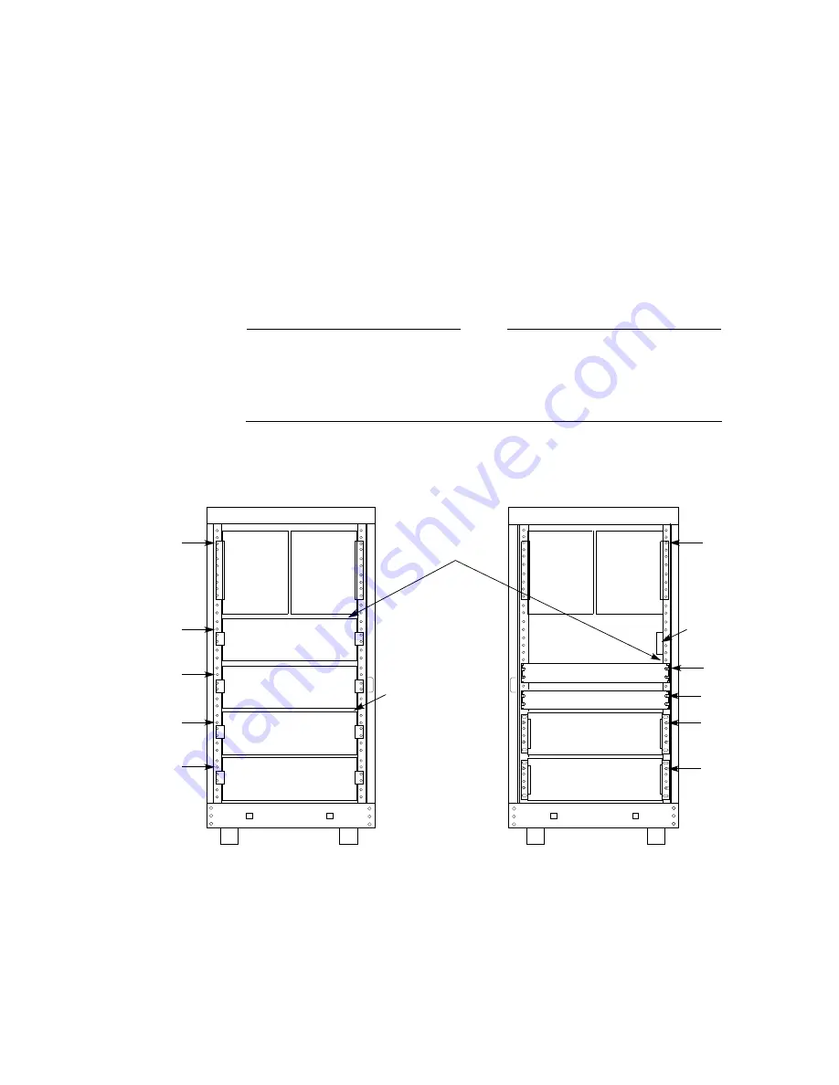
Figure 5–2 shows the proper cabinet rail mounting holes for each shelf location
when TZLX-series tape drives are installed. Mounting hole numbers are counted
from the top of each rail. The hole number assignments shown in the figure
identify the mounting holes for each shelf’s
top
bracket screw and for the
round
standoff
slide locating hole for the TZLX-series tape drives. Refer to Chapter 6 for
detailed procedures pertaining to the mounting of StorageWorks shelves. Refer to
Chapter 7 for detailed procedures pertaining to the mounting of TZLX-series tape
drives. Note that the TZLX-series tape drive extends from the front to the rear
of the SH043 cabinet and utilizes the upper two shelf mounting positions on each
side.
Note
The SHxzz–zz controller/storage shelf consists of a controller shelf with
an attached storage shelf. In systems using SHxzz–zz shelves and TZLX-
series tape drives, storage positions S1 and S4 are physically attached to
and are dedicated to their respective controllers.
Figure 5–2 SH043 Controller/Storage Cabinet Shelf and Tape Drive Locations
CXO-3957A-MC
MOUNTING
LOCATIONS
MOUNTING
LOCATIONS
CONTROLLER
POSITION C2
STORAGE
POSITION S5
STORAGE
POSITION S4
CABINET FRONT
CABINET REAR
HOLE
#22
HOLE
#26
HOLE
#32
HOLE
#3
STORAGE
POSITION S3
CONTROLLER
POSITION C1
STORAGE
POSITION S1
STORAGE
POSITION S2
HOLE
#3
HOLE
#20
HOLE
#26
HOLE
#32
HOLE
#14
FRONT-TO-REAR
SCSI-2 CABLE
ROUTING POINTS
TZLx-SERIES
TAPE DRIVE
POSITION T2
TZLx-SERIES
TAPE DRIVE
POSITION T1
TZLx-SERIES
TAPE DRIVE
POSITION T1
TZLx-SERIES
TAPE DRIVE
POSITION T2
HOLE
#19
CDU A
CDU B
INTERNAL
CI CABLE
ROUTING
POINT
CI BULKHEAD
Configuring SH043 Controller/Storage Cabinets
5–3


