Page 16
CP590
NMEA CONNECTIONS
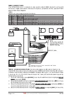
The CP590 PWR ACC 1 connector is also used to attach NMEA devices* such as AIS
Receivers, digital instruments, Personal Computers, autopilots and the optional FF525
BLACK BOX FISH FINDER.
*NOTE
RS232 not opto-isolated electrical interface.
Note:
Gray and White wires should not be connected to other devices
when the FF525 is connected.
Pilot
AIS Receiver
PC
NOTE:
The Tee cable is supplied with
the FF525. If the F 525 is not
connected, plug the Accessory
cable directly into the
PWR ACC 1 connector.
F
GPS ANT PWR & ACC 1
ACC 2
VIDEO OUT
VIDEO IN 1
VIDEO IN 2
PWR ACC 1 Cable
Black
Fuse
Switch
Red
+
BATTERY
-
Green
Gray
Blue
Brown
White
Yellow
Transducer
NMEA Common
Port1 Input
Port1 Output
Port2 Input
Port2 Output
Port3 Output
FF525 Fish Finder
BLACK
RED
GREEN
BLUE
BROWN
GRAY
WHITE
YELLOW
PIN WIRE COLOR FUNCTION
Battery Ground
Battery Positive
NMEA Common
Port1 Input
Port1 Output
Port2 Input
Port2 Output
Port3 Output
1
2
3
4
5
6
7
8
*
**
CONNECTION EXAMPLE
Common (ground) for NMEA devices*
Connect to Output of NMEA device*
Connect to Input of NMEA device*. Default is NMEA-0183 with GLL, RMB, RMC and XTE sentences
Connect to Output of NMEA device*
Connect to Input of NMEA device*. Default is NMEA-0183 with GLL, RMB, RMC and XTE sentences
Connect to Input of NMEA device*. Default is NMEA-0183 with APA, APB, XTE, COG and BOD sentences
Dua
l Fre
que
ncy F
ish F
inde
r
Dual F
requency Fish Finder
*
NOTE: AIS RECEIVER OPTION
(for more information on AIS refer to Section 14)
The CP590 has to be set up to be able to receive NMEA information from the AIS receiver.
The GPS Chart Plotter reads the AIS NMEA message VMD, type 1, 2, 3 and 5 for AIS Class
A and type 18, 19, 24 for AIS Class B. Select the used port and transmission speed by
following the procedure:
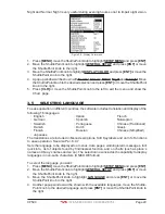
1. From the Chart page, press
[MENU]
, move the ShuttlePoint knob to highlight
SETUP
MENU
and press
[ENT]
.
2. Move the ShuttlePoint knob to highlight
ADVANCED SETUP
and press
[ENT]
or
move
the ShuttlePoint knob to the right.
3. Move the ShuttlePoint knob to highlight
IN/OUT CONNECTIONS
and press
[ENT]
or
move the ShuttlePoint knob to the right.
4. Move the ShuttlePoint knob to highlight
PORT1 INPUT
and press
[ENT]
or move the
Summary of Contents for CP590
Page 1: ......
Page 2: ...CP590 12 WAAS GPS Chart Plotter Owner s Manual GPS Chart Plotters ...
Page 5: ...Page 6 CP590 ...
Page 33: ...Page 34 CP590 ...
Page 43: ...Page 44 CP590 ...
Page 47: ...Page 48 CP590 ...
Page 57: ...Page 58 CP590 ...
Page 73: ...Page 74 CP590 ...
Page 77: ...Page 78 CP590 ...
Page 103: ...Page 104 CP590 ...
Page 117: ...Page 118 CP590 ...
Page 123: ...Page 124 CP590 ...
Page 127: ...Page 128 CP590 ...
Page 134: ......

