


SSI700 User Manual Operation, Display and Application Example
www.ssinverter.info
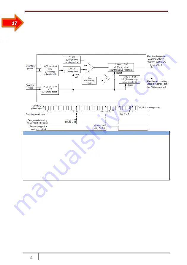
4.6.10 Use of the Counting Function
The count value needs to be collected by the DI terminal that is allocated with function 25.
When the count value reaches 11-08 (Set count value), the DO terminal allocated with
function 8 (Set count value reached) becomes ON. Then the counter stops counting.
When the count value reaches 11-09 (Designated count value), the DO terminal allocated
with function 9 (Designated count value reached) becomes ON. The counter continues to
count until "Set count value" is reached.
Figure 4-28 Parameter setting in the counting mode
Notes
• 11-09 (Designated count value) must not be greater than 11-08 (Set count value).
• DI5 must be used when the pulse frequency is high.
• The DO terminal that is allocated with function 9 (Designated count value reached) and the
DO terminal that is allocated with function 8 (Set count value reached) must not be the same.
• In the RUN/STOP state of the AC drive, the counter will not stop until "Set count value" is
reached.
• The count value is retentive at power failure.
• An automatic stop system can be implemented if the signal output by the DO terminal with the
function (Count value reached) is fed back to the DI terminal of the AC drive with stop function.
4.7 Setting and Auto-tuning of Motor Parameters
4.7.1 Motor Parameters to Be Set
When the AC drive runs in the vector control mode (P0-00 = 0 or 1), accurate motor
parameters are required to ensure desired driver performance and running efficiency. This
is extremely different from the V/F control (P0-00 = 1).
Motor parameters (motor 1 by default) that need to be set are listed in the following table.
Table 4-2 Motor parameters to be set
Summary of Contents for SSI700
Page 1: ......
Page 3: ...Safety Information and Precautions...
Page 7: ...Product Information...
Page 12: ...Mechanical and Electrical Installation...
Page 19: ...Operation Display and Application Examples...
Page 42: ...Function Code Table...
Page 64: ...Description of Function Codes...
Page 131: ...EMC...
Page 137: ...Selection and Dimensions...
Page 141: ...Maintenance and Troubleshooting...