


6-57
DMS-B150L/B210S/B80L/B110S/EX150L/EX210S
6-11. Installing the Package Supporting
Equipment
To install the equipment supporting Package, the drive
stage panel and the tabletop must be removed beforehand
as shown before. Upon completion of installation of the
PetaApp supporting equipment, install the drive stage
panel and the tabletop back by reversing the steps of
removal. (Refer to “6-2. Removal and Installation of the
Cabinets.)
Installation flow chart
n
If the unit is used in the area except above, please contact
your local Sony Sales Office/Service Center.
Yes
No
Installation of the DMSA-TS08/TS16
(Refer to Section 6-11-1.)
Installation of the DMSA-EH16/EHAC/EHACK
(Refer to Section 6-11-2.)
Installation of the DMSA-AT80
(Refer to Section 6-11-4.)
Installation of the DMS-PCU1
(Refer to Section 6-11-5.)
Installation of the DMS-FSW24/28
(Refer to Section 6-11-6.)
Using the drive of the FC model
Installation of the DMSA-CBJ80/CBJ15/CBJX
(Refer to Section 6-11-3.)
(For customers in Japan only.)
Installation of the DMSA-SBE1
(Refer to Section 6-11-7.)
(For customers in Japan only.)
6-11-1. Installation of the DMSA-TS08/TS16
DMSA-TS08 :
Install it in the DMS-B80L/B110S/EX150L/EX210S.
DMSA-TS16 :
Install it in the DMS-B150L/B210S/EX150L/EX210S.
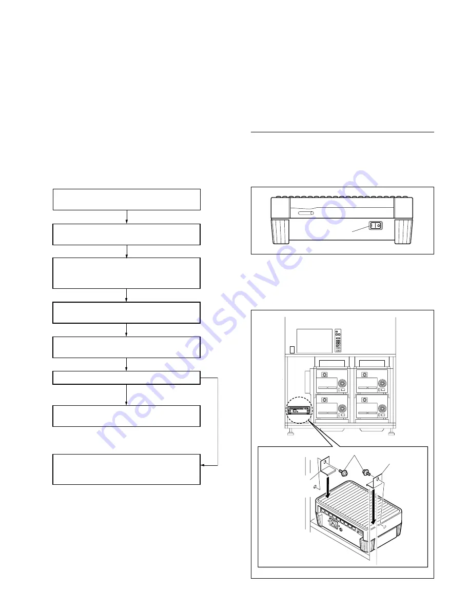
When Installing the DMSA-TS08 in the Basic
Console (B80L/B110S)
1.
Set the POWER switch of the DMSA-TS08 to the I
(ON) position.
2.
Place the DMSA-TS08 at the specified position of the
console as shown in the illustration, and fix the
terminal server bracket (80/ETS8) with the two screws
(PWH4
x
8).
POWER switch
PWH4
x
8
Terminal server
bracket (80/ETS8)
Terminal server
bracket (80/ETS8)
6-11. Installing the Package Supporting Equipment


