A-4
Appendix
Appendix
External Microphone Kit
External Microphone Kit
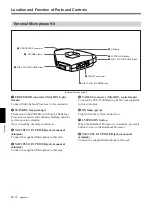
1
PROCESSOR connector (Mini DIN, 8-pin,
female)
Connect the Rollabout Processor to this connector.
2
STANDBY lamp (orange)
Flashes when the POWER switch on the Rollabout
Processor is pressed and continues flashing until the
system goes into standby.
Once in standby, the lamp remains on.
3
MIC2 PLUG IN POWER jack (monaural
minijack)
Connect the supplied Microphone to this jack.
4
MIC1 PLUG IN POWER jack (monaural
minijack)
Connect the supplied Microphone to this jack.
5
TABLET connector (Mini DIN, 6-pin, female)
Connect the PCS-T500 Drawing Tablet (not supplied)
to this connector.
6
ON lamp (green)
Lights when the system is turned on.
7
SYSTEM ON button
When the Rollabout Processor is in standby, press this
button to turn on the Rollabout Processor.
8
MIC3 PLUG IN POWER jack (monaural
minijack)
Connect the supplied Microphone to this jack.
Location and Function of Parts and Controls
4
MIC1 PLUG IN POWER jack
1
PROCESSOR connector
2
STANDBY lamp
3
MIC2 PLUG IN POWER jack
7
SYSTEM ON button
5
TABLET connector
6
ON lamp
8
MIC3 PLUG IN POWER jack
Summary of Contents for PCS-5100
Page 8: ...Features 8 Features ...


