Drive Optimization with HMI Advanced
14.4 Frequency response measurements
Manual
Commissioning Manual, 05/2008, 6FC5397–4CP10–4BA0
517
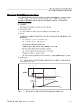
Measurement: Setpoint/disturbance step changes
The transient response (response to setpoint changes or disturbances) of the speed control
in the time range can be assessed with the step stimulation function. The test signal is
connected to the speed controller output for recording of the response to disturbances.
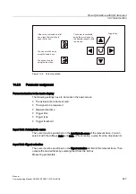
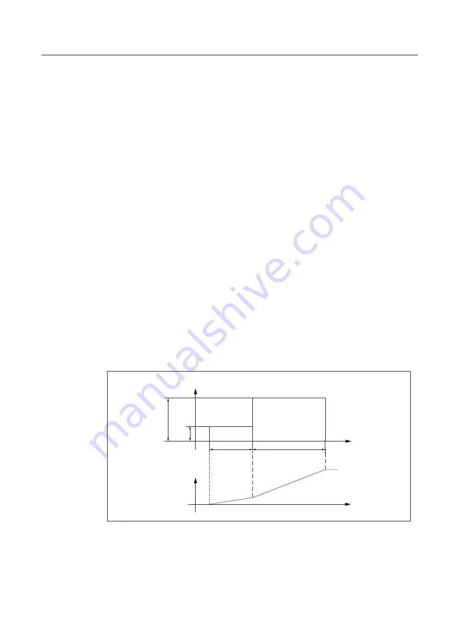
Measuring parameters
●
Amplitude
Magnitude of the setpoint or disturbance step change.
●
Measurement time
The period of time recorded (maximum: 2048 speed controller cycles).
●
Offset
To exclude the influence of static friction, an offset of a few motor revolutions per minute
is sufficient.
–
The offset is run up via an acceleration ramp.
–
The acceleration value is defined for one
Axis: MD32300 $MA_MAX_AX_ACCEL
spindle: MD35200 $MA_GEAR_STEP_SPEEDCTRL_ACCEL
MD35210 $MA_GEAR_STEP_POSCTRL_ACCEL
–
The following applies: Acceleration value = 0, no ramp
Acceleration value > 0, ramp is active
–
The actual measuring function becomes active only when the offset value is reached.
●
Settling time
This value represents the delay between measured data recording / setpoint output and
the injection of the offset.
6SHHGVHWSRLQW
$PSOLWXGH
2IIVHW
6HWWLQJWLPH
0HDVXUHPHQWWLPH
7LPH
3RVLWLRQ
FKDUDFWHULVWLF
7LPH
Figure 14-3 Setpoint course for speed control loop/step response measuring function

