Drive commissioning (SINAMICS)
9.3 Example for systems with more than 6 drives
Manual
Commissioning Manual, 05/2008, 6FC5397–4CP10–4BA0
335
9.3.3
Drives of Control Unit 2: Additional BICO interconnection
The infeed can be connected with a Control Unit via DRIVE CliQ. As Control_Unit_1 is
connected to the infeed, there is no possibility for the drives (drives_6..._9) controlled by
Control_Unit_2 to undertake a BICO connection of drive parameter "p864, BI: Infeed
operation" on the infeed signal "r863: Bit0, Infeed operation":
●
Drive: p864, BI: BI: Infeed operation
●
Infeed: r863: Bit0, Infeed operation
General procedure
In order to use the infeed signal for the drives controlled by Control_Unit_2, it must be
transferred via an external interconnection from an output terminal of Control_Unit_1 to an
input terminal of Control_Unit_2.
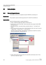
Implementation
The following input/output terminals of the control units are used as an example for the
following description:
●
Control_Unit_1: p738, BI: CU signal source for terminal DI/DO 8 (X122.7)
●
Control_Unit_2: r722: Bit0. CO/BO: CU digital inputs, status: :DI 0 (X122.1)
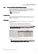
Perform the following actions to interconnect the drive parameters with the infeed signal:
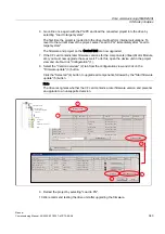
1.
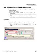
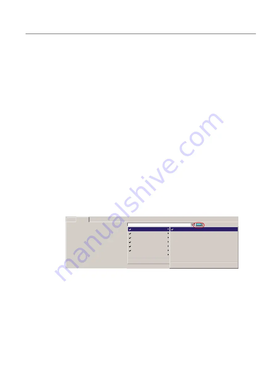
Connect via BICO interconnection the infeed signal "r863: Bit0, Infeed operation", Project
> Drive unit_Adr10 > Infeeds > Infeed > Diagnosis > Connections > Tab "BO/CO" >
Signal: "r863: Bit0, Infeed operation" with the parameter for the output terminal (X122.7)
of the Control_Unit_1 "p738, BI: CU signal source for terminal DI/DO 8"
%2&2
%,&,
U%LW,QKLELWJHQHUDWRURSHUDWLRQ
U%LW,QKLELWPRWRULQJRSHUDWLRQ
U%LW(QDEOHRSHUDWLRQ
U%LW212))
U%LW&RQWUROOLQHFRQWDFWRU
U%LW212))
)XUWKHULQWHUFRQQHFWLRQV
S%L&8VLJQDOVRXUFHIRUWHUPLQDO','2
S%L&8VLJQDOVRXUFHIRUWHUPLQDO','2
S%L&8VLJQDOVRXUFHIRUWHUPLQDO','2
S%L&8VLJQDOVRXUFHIRUWHUPLQDO','2
S%L&8VLJQDOVRXUFHIRUWHUPLQDO','2
S%L&8VLJQDOVRXUFHIRUWHUPLQDO','2
S%L&8VLJQDOVRXUFHIRUWHUPLQDO','2
S%L&8VLJQDOVRXUFHIRUWHUPLQDO','2
,QIHHG
&RQWUROB8QLWBS%L&8VLJQDOVRXUFHIRUWHUPLQDO
'ULYHB
'ULYHB
'ULYHB
'ULYHB
&RQWUROB8QLWB
'ULYHB
U%LW,QIHHGRSHUDWLRQ
)XUWKHULQWHUFRQQHFWLRQV
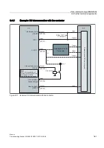
Figure 9-7
STARTER: Work area (excerpt)
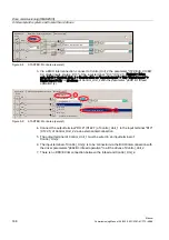
2.
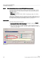
Configure the bidirectional digital input/output: "DO 8" (X122.7) of Control_Unit_1 as
output:
–
Project > Drive_Unit_Adr10 > Control_Unit_1 > Double-click: "Inputs/outputs" > Tab:
"Bidirectional digital inputs/outputs" > DO 8 or X122.7 = output

