
840Di-specific data and functions
18.2 Expanded message frame configuration/evaluation of internal drive variables
Manual
590
Commissioning Manual, 05/2008, 6FC5397–4CP10–4BA0
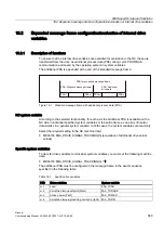
General system variables
The entire message frame with standard process data and additional process data is
transferred in a general system variable as an array of 16-bit integer data words via:
●
MD36730 $MA_DRIVE_SIGNAL_TRACKING[n] = 2
●
System variable: $VA_DP_ACT_TEL[n, a]
where n = Index: 0,2,...15
a = machine axis identifier
Note
•
The message frame configuration must meet the following condition:
(Standard PDA + Additional PDA) - 1 ≤ n
where n = maximum possible index for system variable $VA_DP_ACT_TEL
•
When using the system variables $VA_DP_ACT_TEL[n, a] in a user program, it is only
permissible to use one constant as index n.
Application example for system variables in a synchronized action:
IDS=1 DO $AC_MARKER[0] = $VA_DP_ACT_TEL[12, X]
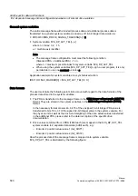
Data formats
The user must take the following points into account with regard to the data formats of the
process data stored in the system variables:
●
The PDA is transferred to the message frame in the 16Bit integer without prefix (UINT16)
format. They are stored in the system variables in the 32Bit-Integer with prefix (INT32)
format.
In the necessary format conversion, bit 15 of the unsigned 16-bit integer PDA value is
transferred to bits 16 to 31 of the signed 32-bit integer value in the system variable. For
the physical unit as well as the drive-end weighting of the drive actual values transferred
in the additional PDA, please refer to the data description of the specific drive
documentation.
●
Drive values combined from 2 PDA (16Bit each) are mapped in the $VA_DP_ACT_TEL
system variable to 2 separate data words (32Bit each), e.g.:
–
Encoder 2 position actual value 1 (G2_XIST1)
–
Encoder 2 position actual value 2 (G2_XIST2)
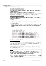
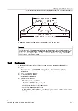
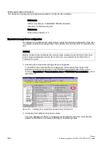
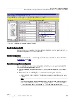
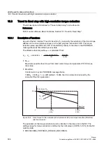
How the process data of the message frame is mapped onto system variable
$VA_DP_ACT_TEL is illustrated by the following figure:


